Wireless Telegraphy 1907
Written by Godfrey Dykes
© RN Communications Branch Museum/Library
The contents of this file 1907/1 are listed below. |
| General Summary - the 'musical note' (for sending Morse code) is now all the rage Musical Notes. Experiments are under way to look for an installation for large ships to send 'musical notes' (spark with AC alternator of high alternating frequency (our AC today is 230V 50Hz {50c/s)) and we sometimes talk about a 50Hz 'hum'. What about a 'hum' of 400Hz ? The decision on this more powerful humming apparatus became known as SERVICE INSTALLATION Mk 11 and 43 sets were on order for delivery in 1908, whilst from 1915, comes this handbook for the system with many amendments and some reprints through the years (front cover of book and page one only) Type II WT INSTALLATION. 110 ships now issued with rotaries (AC alternators) creating AC from the DC ring-main or from batteries. Tuned Shunts are now the norm in the Fleets - band-pass/band-stop receiver aerial filters. See this file for details Receiver Aerial Filters A large number of ships now have a silent cabinets fitted into the W/T office. 35 ships have top-gallant masts with W/T yards for supporting modern heavy aerials and insulated rig fittings. W/T Offices now ready to receive Service Installation Mk II. 10 ships have the powerful multi-Tune 'C' Tune apparatus. 'C' Tune is a great success story and achieves ranges in excess of 250 miles on Tunes 'S' 'T' and 'U'. Destroyers now fitted - 'River' class and ocean going destroyers already to go. Portsmouth dockyard now has a repair shop for W/T instruments with a HMS Vernon officer in charge. The new branch of the Telegraphists has been formally introduced. The training of boys for this Branch is steadily progressing in the Training Ship Impregnable. The first class of Boy Telegraphists will be drafted to sea in May 1908 and after that date, a class of about twelve boys will pass out every four weeks. Communications operating and equipment guidance books are required soonest. This was a typical preface in the books of this time Typical preface to books of early WT. Commercial W/T - International Convention [eventually the ITU] has established [which comes into force July 1908] an agreement which brings together ships and shore stations of all nations to work as one in matters of W/T. The Convention was held in Berlin in October and November 1906. Britain ratified the Convention in July 1907. International Radiotelegraphic Convention, the very start of the ITU, ratified by 27 countries. Notice that the final section, on file page 6, "Final Protocol" that Great Britain, under clause II, reserves their Power along with eight other nations. |
- - - - - - - - - - - - - - - - |
The contents of this file 1907/2 are listed below. |
| Embryo ITU Regulations. Morse code prosigns given in this section are:- a. Commercial interrogative - Naval interrogative is ( dit dit dah dit dah ). b. End of working (no more messages). c. Distress Call. d. Use groups from INTCO (International Code of Signals) to communicate. e. Commercial Telegram. f. Roger (I have received your message). g. End of this message using Broadcast method, or, on non-Broadcast method, end of session with neither side having traffic to send. |
- - - - - - - - - - - - - - - - |
The contents of this file 1907/3 are listed below. |
| Report of W/T Conference held in HMS Vernon 31st October 1907. More telegraphists needed with a rapid increase in personnel. Operators - intelligent men are far better than machines. Two operators on watch at a time in W/T Offices, one to code and decode/cipher and decipher and to look after ongoing W/T chores, and one to do the operating in the silent cabinet - transmitting and receiving. (Note coding/decoding applies to W/T codes - like operating signals, INTCO groups and the groups outlined in the HYPERLINK below, whilst ciphering/deciphering applies to protecting secret signals). Both operators should be telegraphists so that they can alternate between both jobs. The non-silent cabinet operator can wear earphones (called telephones) outside the silent cabinet in parallel with the set worn by the silent cabinet operator, to jointly read the same incoming Morse code. CL100 is the ships Complement List giving numbers allowed in the ships company. 100 non-signal branch (V/S ratings) rating volunteers from all branches required urgently to change over to the telegraphists branch. Instruction for the conduct of W/T signalling Book laid down with W/T procedures. Superintendent of Signals Schools (in HMS Vernon) to manage W/T Procedure Books. Secret signals should be ciphered and all others sent in Service Code where pre-ordained groups of letters and figures represented a sentence, a phrase, a place, an order or a command. See this page 19TH CENTURY WIRELESS TELEGRAPH OVERALL, choose 'Before 1895.......", scroll down to roughly half way until you see "What follows" (in red) and there you will see a typical code of the type I have mentioned here. Ciphering/deciphering was all done using books (one time pads (OTP) etc). A system was sought whereby ciphering/deciphering could be done mechanically on a device like a typewriter. Precedences were not yet used at this stage, and signals were dealt with as received - Service Code was easier to handle than was cipher code which was often the more important of the signals received but left to the last to decipher. 'War Books', all well and good, but what would happen were they to fall into enemy hands ? Destroyers (with only the one operator) to be treated differently to big ships - no signal code but simply to cipher a transposed alphabet. Big ships, during busy periods, employ clerks to decode-encode/decipher-cipher and to do the logging, and when not available, junior officers should do the job. Flotilla Signal Book and Supplementary Signal Code should be made available to all ships for constant use. Signalling Position - 'War College Method' adopted. Organisation of wave lengths. Dealing with interference/jamming - use of another ship as a relay, but not recommended. Better to use V/S or excuse one ship from W/T duties so that it can concentrate on being a 'relay ship'. Battleships should dismantle their W/T offices and transport the gear to a safe place below decks before opening fire on the enemy. This will take 2 hours for a Service Mk1 installation (small) and 1 full day for the Service Mk11 installation (large). After action, W/T office restored to its former operating position. If gear wrecked, a jury W/T transmit and receive station should be rigged on deck utilising spare parts. Short distances communications between ships of a battle squadron at night without showing a light is necessary and should be researched in HMS Vernon. (This would be likened to tactical communications on V/UHF frequencies in a modern navy). Inter-Fleet W/T exercises to start. To involve shore stations in inter-Fleet exercises requires the permission of ACR (Admiral Commanding Reserves). 'Q' and 'R' Tunes should be modified by 1st January 1908, to be 2000 feet and 2600 feet respectively 485 kHz approx and 380 kHz approx, in accordance with the fledgling ITU (International Telecommunications Union) regulations which come into force in July 1908. Naval ships should communicate with commercial shore stations occasionally so that in wartime they will know their procedures. General improvements - ships in harbours using too much W/T transmitting power which is affecting ships in foreign parts. Buzzer system should be used for harbour W/T exercises. To avoid interference ships to tune transmitters only between the hours of 1100-1200 and 1400-1600. High power Service Mk11 installations should reduce power to achieve 50 miles and this will be introduced in the circuit design of the apparatus. W/T Service Mk1 loss of power/range due to wet/damp and self-assembled oscillators. |
- - - - - - - - - - - - - - - - |
The contents of this file 1907/4 are listed below. |
| Summary of experiments in connection with design and practical trials with Service Installation Mk11 - original trial with 12kW 250 c/s alternator difficult to keep running and spark gaps a continuous source of trouble. However, the Morse note produced was easy to pick out from other signals and atmospherics. Tests with 400 c/s alternators gave a spark range of 250 to 400 c/s where 350 c/s produced the best Morse penetrating note.
Revolving balls/disc physically altered, looking for best Morse note using two spark gaps.
Service Installation Mk11 - diagram of H.T., transmission circuit.
Revolving discs troublesome: new method required. Discs to stop and blast of air used in lieu, directed onto to spark gap - marked improvement!
Further improved note by reducing to one spark gap and an air pressure to completely change atmosphere of spark.
New dielectric required. Mica too expensive. Artificial mica too inefficient. Ebonite tried and immediately found satisfactory.
Possible Tune's listed. To assist you in your read, the following frequencies are associated with Tune P, Q, R, S, T, U, V and W respectively:- 983kHz, 490kHz, 378kHz, 298kHz, 234kHz, 196kHz, 172kHz and 151kHz.
Variation of spark gap size and range trials.
Diagram of various aspects of Service Installation Mk11.
Experiments to investigate changes in capacitance at various frequencies.
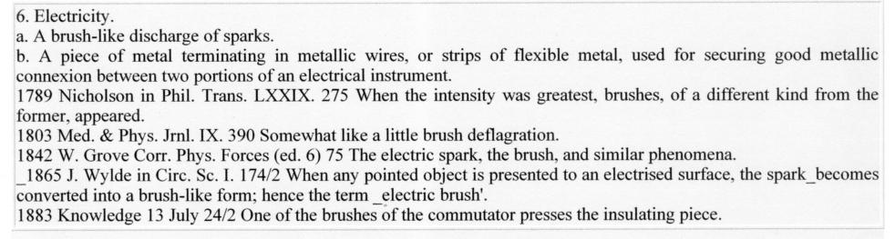
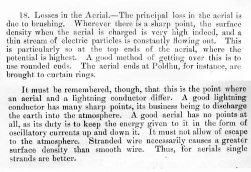
The following text may assist you to understand the much mentioned "Brushing". Brushing, however caused (see para 22 of the second thumbnail) results in wasted resources - power output etc. At this time period, they knew it was happening and roughly what steps to take to cure it, but not why. These text jpeg's are taken from the 1906 Manual of Wireless Telegraphy. The Oxford English Dictionary (OED) shows the following definition in the first thumbnail.
|
- - - - - - - - - - - - - - - - |
The contents of this file 1907/5 are listed below. |
| Service Installation Mk11 - Morse note approximately equal to the 'F' above the Middle 'C' in music, a note indicative of the Royal Navy sending messages. Middle 'C' has a frequency of 264 Hz and 'F' is 352 Hz (352 Hz is also known scientifically in Medical research to be the frequency on which our brain talks to our bladder - that's comforting to know). Other musical notes are 'D' = 297Hz, 'E' = 330Hz, 'G' = 396Hz, 'A' = 440 Hz and 'B' = 495Hz. On a DTMF modern touch tone 'phone the lowest frequency used is 698Hz and the highest 1477Hz. Whilst reading this file you might like some statistics about audio per se. We have visited an American Institution to gets some appropriate sounds and from them we have made a couple of our own sounds files as follows. The first is designed so that you can test YOUR OWN HEARING and whilst at it, bring along the dog. It demonstrates well our exponential hearing LINEAR PROGRESSION OF HEARING.wav which has a beep at the front and the back to tell you when it has started and finished. This will become obvious since we doubt whether you will hear 20Hz or 20kHz. The second Swept Sine Wave sweeps from 20Hz to 20kHz and it too has a start and stop beep. The musical Morse code note achieved on the Service Installation Mk11 of 350 c/s, which made it so distinct from all other notes of that time. As you listen, remember that in the 'modern' R.N., the normal demodulated CW (A1) A.F. tone was 1kHz (1000 c/s) so the Mk11 note would have been VERY LOW at the receiver by comparison. The numbers called out on the following file are of course Hertz or c/s and obviously you will not hear the first couple of calls, the frequency being too low FREQUENCY OF TONES - remember particularly to listen for the note of 320Hz (c/s) which is nearest we could get to 350 c/s and think about the operators of 100 years ago ! Finally a short tuning signal using a Morse Musical Note of 325 c/s 325 Hz Tone. To use a 350 c/s spark gap, between 20 and 25kW will be required while actually signalling. No further advantages can be made so this Installation will be the most powerful possible for a ship. Thin ebonite sheets for transmitting condensers and the powerful air blasts for the spark, have overcome the early difficulties with the installation. The set is compact and safe. It can transmit any wavelength between 1800 feet and 6500 feet (545 to 151 kHz) with full power, and, after 2 minutes change over, on 1000 feet (983 kHz) on reduced power, which today we would call an MF transmitter system. The maximum day time range is on 'T' Tune (234 kHz). Most things in the Installation to be new and enhanced but several parts of the system will be the same as C Tune Mk11. The days of the rotary converters (AC current produced by DC current) have gone and in their place the Fleet will have motor alternators. Ship will get two, one connected and one on standby with the C.O.S. in the W/T office. Re-wiring and re-organisation in W/T office planned with much work for dockyards and ships staffs. Diagram of the W/T Installation Service Mk11. Detailed and specific fitting instructions listed. The main AC circuit will be 80 amps at 400V when signalling - it is to be broken at two points. A shock from the AC circuit will be very severe if not fatal. Thus everything to have covers and locks and what is not so treated will be protected by a safety circuit. Machinery and Instruments to Service Installation Mk11. Diagrams of transmitter condenser. The magnetic key (which has a rapid action) is operated by the Morse key. Diagram of magnetic key. Transmitter instruments in five sections all fully explained. Diagram of Primary (the primary oscillator) connections. DC supply voltages in the Fleet : 80, 100 and 220 V. |
- - - - - - - - - - - - - - - - |
The contents of this file 1907/6 are listed below. |
| Service Installation Mk11. 43 destroyers to be fitted with one staying back with the Mk1 fit because of space constraints. Destroyers have different signalling requirement to those of larger ships/battle groups. New wavelength chosen for their needs to be transmit only on 'D' Tune - 700 feet (1.4MHz) , but to have a new special receiver which will receive all Tunes. Minimum daylight communicating distance should be 50 miles. 1.4 MHz chosen so as to avoid interfering with larger ships/battle groups operating on 983 kHz and below. W/T office to be a large silent cabinet containing all the instruments except for the rotary alternator, to be fitted between mast and foremost funnel to limit amount of effect of smoke and gases, although on some destroyers, it will be sited on the bridge superstructure abaft the charthouse. "ON ACCOUNT OF THE ALREADY LIMITED SPACE AVAILABLE FOR THE MEN'S QUARTERS, AND THE NOISE OF THE SPARK WHEN SIGNALLING, THE OFFICE WILL NOT BE BUILT BELOW THE UPPERDECK." Sketch of destroyer showing aerial array/fit. Signal strengths measured on scale 0-10 (unlike later when scale was 0-5). Text shows signal strengths achieved between destroyer Usk off Portland, and Portsmouth, with Usk steaming at 20 knots, the forward stokehold (immediately beneath the office) buzzing, and lots of sea spray coming inboard. One operator per destroyer and that a Petty Officer Telegraphist. List of destroyers to be fitted with Mk11 Installations. Proposed destroyer organisation of wavelengths. Large ships to take guard (look out for) on W/T circuits to relieve stress on the one operator, but destroyer to stay within V/S range. Guard organisation to be called 'A' and 'B' which is supported by explicit drawings. Proposed improvements in the Service Mk1 Installation Transmitter Circuit for small vessels - they will be able to transmit on all wavelengths of 700 feet to 6500 feet (1.4MHz to 151 kHz). Possible faults in reception apparatus. Remarks on Tuning - Loose/Tight couplings. |
- - - - - - - - - - - - - - - - |
The contents of this file 1907/7 are listed below. |
| General notes on the use of a wavemeter. Curves of rejection inductance. Unsteady Spark - recommend instead of using a LONG (dash, mark, key down condition) for tuning, better to use a rapid series of SHORTS (dots, spaces, key make and break] groups). Earphones can be placed across the wavemeter terminals as a tuning aid and this is recommended. Notes of receiver circuits. Instructions for the use of curves of rejection values - Tune Shunts. Horsea Island experiments with HMS Furious with Long Waves using a spark resonance of 30 c/s at 8kW. Waves were 7000', 8000', 9000', 10000' and 12000' respectively 140kHz, 122kHz, 109kHz, 98kHz and 82kHz. |
- - - - - - - - - - - - - - - - |
The contents of this file 1907/8 are listed below. |
| Radiation from aerials and transmission losses. Freak distances achieved and regularly - no rational explanation! Unexplained and extraordinary ranges obtained at night with short waves! If only they could have known and understood propagation {sky waves, ground waves, skip distances, silent zones, D/E and F Layers of the ionosphere, ionospheric storms and anomalies etc}. Curve value Mk11 rejecters. Travelling Losses - "THIS LOSS MUST DEPEND ON THE STATE OF THE ETHER BETWEEN THE TWO SIGNALLING STATIONS AS IT IS SO VERY DIFFERENT DURING THE DAY AND AT NIGHT; IT MUST THEREFORE BE VARIABLE." "WHEN, DUE TO FAVOURABLE CONDITIONS, THIS VARIABLE TRAVELLING LOSS IS GREATLY REDUCED, IT WOULD BE GREATLY TO THE ADVANTAGE OF THE SHORTER WAVE WHICH WOULD THEREFORE CARRY VERY MUCH FURTHER THAN USUAL WITH THE RESULTING FREAK DISTANCES." Methods of transmitting short waves from long aerials. "AS SHORT WAVES ARE USED FOR SPECIAL PURPOSES IT IS OFTEN NECESSARY TO BE ABLE TO SEND THEM. A SEPARATE AERIAL CAN BE USED FOR THIS PURPOSE BUT ITS USE IS OPEN TO SERIOUS OBJECTIONS AND IS LIABLE TO INTERFERE WITH OTHER WORKS." Proposed SHORT WAVE W/T - "THE SUBJECT OF SHORT DISTANCE W/T IS ONE THAT IS ATTRACTING A GOOD DEAL OF ATTENTION AT THE PRESENT MOMENT" - two problems! [1] Power versus wavelength to achieve 50 miles and [2] power versus wavelength to achieve just 5 miles. This section deals only with the problems of achieving just 5 miles. What the article discusses is a need to, at times, replace V/S [day and night] for messages and manoeuvres, without interfering with Service Installation Mk11, the main [MF] W/T fit - except for destroyers using 1.4MHz the starter end of the HF/short wave spectrum. In short, they were looking for our [modern times] UHF Tactical Communications {225-400MHz}, or, in their words, a wavelength of 29.47 inches to 51.09 inches {mid-band 40.28 inches}. The trials mentioned between Horsea Island and HMS Vernon are using a wavelength of 400 feet [2.5MHz], 400 feet being 4800 inches, just a 9900% difference! Here, they would have been employing the ground wave oblivious to the sky waves being radiated. "SHORT DISTANCE MAY BE OF GREAT USE FOR THE PURPOSES OF HARBOUR DEFENCE." Extract of short distance W/T experiments in the Mediterranean - successfully used for manoeuvres between ships at night steaming in close order without lights. Equipment/aerial fitted in forward conning tower adjacent to Captain's bridge position. Mutual interference problems in each ship between Service Installations Mk11 and Short Distance Equipment, but no affect ship to ship from other ships. No atmospheric disturbances experienced. Sort out the mutual interference, and the exercise was a success. HMS Vernon say that it can do that. |
- - - - - - - - - - - - - - - - |
The contents of this file 1907/9 are listed below. |
| Naval Shore W/T Stations. Naval Stations manned by the Coast Guard (who are also the navy recruiters). Classes of Station. (1) CLASS 'A' - 100 kW, several wavelengths, 1000 miles day and night - 2 in England at Cleethorpes and Horsea Island (for experiments and instructional reasons) - 1 at North Front Gibraltar. They transmit Admiralty orders and information to ships of the Fleets at sea. (2) CLASS 'B' - In England - to keep in touch with Fleets in Home Waters. 40kW - 3 in number at Aberdeen, Pembroke Dock and possibly at Harwich. (3) CLASS 'C' - 100 miles on Service wavelengths convenient to various naval ports. Small Stations List (add Rosyth to it). List of shore stations in the UK for Naval purposes stating which wavelengths they listen to. List of shore stations in the UK for non-Naval purposes unless in an emergency. Note East Coast stations have American (De Forest) equipment. Frequencies 1000' and 2000' (983kHz and 491kHz - the latter, the forerunner of 5 ton (500kHz). Notes on the W/T Stations usually heard by the Naval shore stations and some details with respect to the companies working them. Companies working in Great Britain - A R Co, Chairman is Lord Armstrong the man who built so many fine warships and naval guns/armaments. His factories were famous in the North and his house was the very first in the UK to be electrified. Note the significance of the Marconi entry - English Directors in the main with controlling powers over the whole of the Marconi empire. Stations and who owns them in the UK and abroad. Under Esbjerg and Lyngby, note the two letter callsigns for the Danish steamers. Under Foreign Stations, note the callsigns KND and ORD working with the German High Sea Fleet. Abstract of report of visit to H.P. Station Clifden, Ireland, by officers of the Atlantic Fleet July 1907. |
- - - - - - - - - - - - - - - - |
The contents of this file 1907/10 are listed below. |
I first mentioned Poulsen and his 'Arc TRANSMITTER' in this file Arc Transmitter. The "very safe" 'Arc transmitter' was eventually to supplant the "potentially dangerous" 'SPARK transmitter'. However, although the Navy had chosen to not publish details, by this date (1907) Poulsen had almost perfected his system and before WW1 got going, many USN battleships were fitted with the Poulsen system as were a couple of British submarines for trial purposes. So, at this time there was a great 'race' to abandon the SPARK AGE and to adopt a SPARKLESS AGE, an age which became known as the Arc AGE. More about what this technology was later, suffice to say at this point, that all of you are vaguely familiar with the technique because unlike the intermittent nature of the keyed on and off Spark, the 'Arc system' produced continuous electric oscillations (AC at very high frequencies) which of course became known as CONTINUOUS WAVES or CW.
I have mentioned the great 'race'. In the main that was between a Dane (Poulsen) who had built upon an English invention (Duddell) and an Italian (Marconi). The advantage of the Poulsen Arc in those early days was that it could produce rather NARROW BAND CW signals - generally below 100kHz - for direct application to the antenna. The raw baseband Arc of Marconi - BROAD BAND - produced everything from DC to Giga Hertz (GHz), with its antenna being at best a rather poor filter trying to block unwanted emissions. It didn?t do so very successfully in view of the limited ability of "filters" (tuned shunts) in that early era. Thus, while Marconi transmitter plants had to be built in remote areas, with the construction costs of an entire mini-city and a steam-powered electric generator plant, a Poulsen transmitter could be located right in a populated area that had personnel amenities and commercial electric power at hand.
The Poulsen Arc converter could also produce generally higher fundamental frequencies than a baseband Arc. In any event, they were more pleasant to listen to than the baseband Arc, since they produced an almost pure carrier with a tone superimposed on it. The rendition of dots and dashes was thus a series of long and short tone bursts, something that could not be produced in the receiver in that time before any sort of local oscillator was available. It really could not be keyed on and off; rather, it had to be shifted in frequency, with the receiver tuning in only the wanted, or "forward" bursts. The "back wave," as it was called, was a poor image of the transmission. In extremely simple terms but nevertheless accurate, imagine a continuous oscillation (derived using DC to create AC and a couple of pieces of solid carbon laid end to end with a gap between, over which a permanent Arc is created of even amplitude) and this oscillation connected to a coil which is an integral part of the aerial system circuitry. The coil has several tappings which are connected to various parts of the Morse key. The permanent oscillations and the full coil radiate (remember the "almost pure carrier with a tone superimposed" mentioned just above) on the aerial when the Morse key is NOT PRESSED, a frequency which is the "BACK WAVE" (if you want, the undesirable frequency). When the Morse key IS PRESSED it shorts or opens (I have drawn it open circuited - it is, after all, an extremely simplified explanation !) part of the coil which changes its (and the aerials) output frequency to the "FORWARD WAVE" (the desired frequency) to which the distant receiver is tuned.
|
- - - - - - - - - - - - - - - - |
The contents of this file 1907/11 are listed below. |
| Patents recently taken out in W/T. Everybody is jockeying for position as the evolution unfolds. In this batch 19 for transmitters; 21 for receivers; 5 new coherers and 3 detectors. Have a look at the section headed "Miscellaneous". Many of these they achieved many years ago, but train crashes - ask Rail Network ? Instructional Work - officers and ratings trained in W/T this year. PO Tel courses - frequency and duration. Speed of training through-put important. List of fixtures to be supplied to ships and signal stations abroad fitted with Service Installation Mk11. |