Wireless Telegraphy 1908
Written by Godfrey Dykes
© RN Communications Branch Museum/Library
The contents of this file 1908/1 are listed below. |
General summary of W/T progress during 1908.
Mk 11 installed into a number of ships, in the Admiralty and St Angelo (Malta), and will be working in the Aberdeen, Pembroke Dock and Ipswich shore W/T stations by the middle of 1909.
A 100kW transmitter has been designed for Cleethorpes (the most important of all naval shore W/T stations), Horsea Island and Gibraltar with day time ranges averaging 1000 miles for large ships, and each has a Special Tune capable of being received by ships with a Mk11 aerial.
Service Installations Mk 1* design and work continues. Mk1 whilst widely fitted was still considered as 'test gear'. The Mk1* denoted that the installation was now recognised as pukker fit.
Trials in HMS Vernon of the Arc system culminated with a resounding "not good enough for the navy", and no further serious thoughts would be entertained.
Portable W/T equipment trials.
Much thought given to W/T signalling and the W/T signalling book.
Petty Officer Telegraphist courses in HMS Vernon and Boys courses in HMS Impregnable are proceeding at a good pace. However, the numbers are still much too low "becoming daily more serious and difficult to solve."
Instructional report - officers and ratings trained in W/T. Note the Branches of the students.
Telegraphists Branch. Number in the Branch as at 21.11.1908 - notice the ratios especially that between Ldg.Tels and PO Tels !
Extract from report by the Captain of HMS Impregnable on the training of Boy Telegraphists. By 1908, 259 boys classed up, 44 discharged from classes (for failure at studies, misconduct, invaliding, discharge by purchase etc.) SLOW Drafting ? "22 boys who passed out in September 1907 are still awaiting drafts to the Mediterranean Station, but will proceed to join HMS Bacchante on the 24th October 1908.
Extract W/T Conference 21.9.1908 held in HMS Vernon.
Voice pipe communications between short distance W/T office and fore bridge for manoeuvring. Need to check up on W/T operators accuracy in receiving signals. Some indication should be provided so that operators know whether or not, that their aerial is indeed sending signals. Signal Pad (S1322) still OK for its intended use and shouldn't be altered.
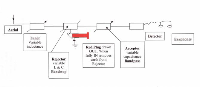
The "Red Plug" has been invented which stops the operation of the main W/T system (Service Mk11) RECEPTION from operating when the short distance W/T installation is operating and vice versa. When the 'plug' is "OUT" the SHORT DISTANCE W/T office was used and if "IN" the MAIN W/T office was used. However, in unsure conditions of operating (dense fog in company) both could be used just to ensure communications where clearly V/S could not be used. The Red Plug was built into the TUNED SHUNTS (mentioned in 1907). Tuned Shunts consisted of an ACCEPTOR and a REJECTOR coupled together so as to cut our interference when receiving signals on either a Magnetic Detector or an Electrolytic Coherer. They were each and separately tuned to the Tune being received and were connected between the Aerial and Earth, the aerial also being separately tuned to the Tune. Today, we could show that as a simple block diagram as follows.
|
- - - - - - - - - - - - - - - - |
The contents of this file 1908/2 are listed below. |
Naval shore W/T stations.
High Power - Medium Power and Low Power Stations - definitions of.
Typical arrangements - masts, aerial, and earth at Aberdeen medium powered station. Geographic areas of coverage diagrams.
Note, under low power, that private telegrams were allowed from HM ships even at this early stage in development.
Note, the frequency of the Morse code tone as being the equivalent to the musical note middle 'C' (= 264 Hz), but actually declared as 250 Hz. Wavelengths are 10000 and 12000 feet (98kHz and 82kHz).
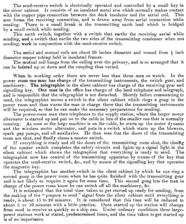
Mains power connecting cable to Horsea, Cleethorpes and Gibraltar, all with off-site power stations/sources, are respectively 3.5 miles long, 3 miles long and 2.25 miles long, the power for Horsea and Gibraltar coming from the Dockyards, and for Cleethorpes, from the Grimsby Corporation. Details of the Stations and how they were laid out, operated and manned. Have a look at these two text snippets-
 |
- - - - - - - - - - - - - - - - |
The contents of this file 1908/3 are listed below. |
| Remarks on Service Installation Mk11. Noisy equipment - how to get round it. Other problems and the faults resolved. Improvements in the later design of the instruments. Arrangement of Trunk. Adjustments of Service Installation Mk11. The FIRST MENTION in this, the record of naval trials in W/T, of the VACUUM TUBE - the now proverbial thermionic valve....... Vacuum Tube used to indicate if aerial is not radiating. |
- - - - - - - - - - - - - - - - |
The contents of this file 1908/4 are listed below. |
| Service Installation MK1* Improvements made to this now aging equipment of Mk1. No fewer that 114 ships will benefit. Enhanced fit will be known Mk1* (star). Fits in the Fleet will now be:- a. Service Mk11 - for all new and large ships b. Destroyer Fit - 'D' Tune transmit and all Tunes receive c. Service Mk1* - for many existing ships not large enough to be fitted with Service Mk11. Goodbye to 'C' Tune 11 and in its place will be fitted Service MK11. Short distance W/T. Future policy - ships to be fitted. Where the office will be fitted and what it will consist of. To sum up, read the last sentence of the file re replacing V/S. |
- - - - - - - - - - - - - - - - |
The contents of this file 1908/5 are listed below. |
| Electrolytic detector - is it suitable for Service use ? Destroyer Installation. 45 fits delivered and 35 fits installed. List of the ships fitted and the Fleet to which they belong, followed by ships to be fitted. Recent improvements. Failures that have occurred and their causes. Visits of officer from D.N.O. Admiralty and HMS Vernon to Clifden (Ireland) 3/4 February 1908 - technical details. Description of the transmitter - fascinating ! Read about the Power Plant and the peat diggers. Description of the receiving instrument. General notes on the station - not favourable ! Earth - nearby water source not sea water but, because of peat, its absorption caused 'acid water' and it is said to be an excellent conductor. Points of interest obtained during conversation with Mr Marconi. Comments hinting back to an Arc transmitter - "continuous oscillations". Note: Marconi talks about the effects of the "ionisation of the sunlight" - the wet sheet theory!......"Again, during stormy weather it is difficult to tell which wave will get through." This he considers, is due to streaks or banks of ions being blown about irregularly by the wind, the distribution sometimes allowing the shorter wave to pass whilst the longer one is impeded and vice versa. He is near to understanding the ionosphere, but a million miles away from applying the perceived theory in a practical manner. Information required from the Marconi Company. The Admiralty wants to know what is going on at Poldhu and what Marconi's many experiments are about. Poldhu visited 11.2.1908 but little change has taken place since the last visit in 1907. Detail about the station. Lizard visited - very primitive. Very little has progressed in the past few years. |
- - - - - - - - - - - - - - - - |
The contents of this file 1908/6 are listed below. |
| Lodge Muirhead Portable Wireless Set. First mention of Electric Valves (as opposed to the Americanism of vacuum tubes). However, they are said to be unreliable and can easily be damaged. Note the Dynamo entry: I'll take the Morse key and you can take the bike ! Up to now, it has all been WIRELESS TELEGRAPHY but now WIRELESS TELEPHONE (Telephony) comes onboard. Mr De Forest arrives from the USA for a European demonstration tour. He brings with him his new fangled WIRELESS TELEPHONE system which is called a Type C radiating 1 kW, and his wife. In France his speaking system wins much praise leading to comments like "leaving nothing to be desired". In particular a receiver detector called a "Audion" was an outstanding success. De Forest moves to Italy to the Italian navy. Excellent voice quality is received at some distance and this with high ground (1500 feet) between transmitter and receiver aerials. De Forest comes to the UK. Wireless Telephone fitted in HMS Furious for transmission (operated personally by De Forest). Receiver site in HMS Vernon, personally operated by Mrs De Forest. Additional trials using HMS Niger and HMS Velox produced such IMPORTANT RESULTS that they are to be kept Confidential. HMS Furious/HMS Vernon results show potential. Both the USN and the RN have commented that Wireless Telephone and Telegraphy grossly interfere with one another. Other limitations are stated. RN interested in further trials of its own and seeks legal advice about the Patent in the UK. Poor old POULSEN! The Navy has another look at his system. Third mention since the record began. Extract from HMS Vernon - Experiments with the Poulsen Arc system. Trials involving HMS Vernon, HMS Furious and Cullercoats W/T station with POOR results. Look at the NOTE underneath Fig.1., - quite frightening to frequency/wavelength planners I would have thought ! The extremely poor results achieved (with the Arc equipment manufacturers present and doing the alignment and operating) led to the navy abandoning the trials as the experiments were "a complete failure". These comments applied equally to both Wireless Telegraphy and Telephony. Poulsen Arc Telegraphy - report on demonstration of high-speed reception by photographic means. In this case, photographic means ink-recorder or printer. Cullercoats W/T shore station, near Newcastle, mooted that warships transmitting on naval Tunes in the areas off the Tyne, blocked out their normal means of reception from Denmark i.e., wearing earphones to listen to audible Morse code symbols created by hand signalling, but that they could receive these signals using a (ink) printer. The top speed of Morse transmission was 99 wpm. For stability reasons it couldn't be used at sea, but wherever it was used, the recording had to be deciphered (played back) by an operator. This reminded me of my time in submarines when we recorded high speed Morse from Rugby on VLF (GBR on 16kHz) on one speed, then slowed the machine down so that the played-back Morse code could be transcribed with a pencil. In this article, in two places, it loosely mentions quartz crystal (or stones) as applied to detection of signals - crystal detectors ?....cats whiskers......things yet to come! Note the Christiansen (Kristiansen) Detector. A crystal detector many years later was a crystal touched by a very fine wire wrapped around a former as a coil, known as a cats whisker. Here we see the crystal and the fine wire is a piece of graphite. Hardmuth was a very famous manufacturer of pencils and since his were the best, the diamond of all pencils, he called them his Koh-i-noor. The other crystal detector, the Perikon, can be found under the section "Articles under Trial" - it refers to crystals as SPECIAL STONES. As for wavelengths radiated from an Arc transmitter, we have already explained this phenomenon in this file Click Here. The working wave is the "FORWARD WAVE" to which the distant receiver is tuned. All the other waves are by-products of a Continuous Wave (CW). Note that 4940 feet, the fundamental "BACK WAVE", is 6.5% below in λ and above in frequency, which is a calculated shift on the coil tappings. Experiments carried out in HMS Vernon to ascertain the best method of sending out a short wave (700 feet) from a long aerial using a Service Mk1 set. Tuning to Tunes 'D' and 'P' in ships other than Torpedo Boat Destroyers. Receiving short waves. |
- - - - - - - - - - - - - - - - |
The contents of this file 1908/7 are listed below. |
| Fleet W/T exercises in the Mediterranean. Comments on accuracy of signalling and coding/encoding. Necessity for brevity in signals. Press telegrams (?) not properly prepared for sending by W/T. Opsig IMI used wrongly by operators when they haven't missed any part of the message but want it repeated because the signal is not understood. No verify procedures in place. Brevity necessary in signals in the Home Fleet. Experiments with extemporised (not prepared - off hand) wireless in Sheerness Port Defence Flotilla. 500 feet to be used (1.79MHz) and 850 feet (1.15MHz). Good results and provision being made to design and build a Harbour Defence Set. Local effects of land masses in and around the UK. Reports from shore stations on atmospherics - Essex Hill Alderney and Felixstowe. Pr?cis of report on W/T work carried out in connection with the suppression of piracy in Canton China. W/T Office on destroyer torpedo boats to be 6' x 5' x 6' 6" high. Bamboo masts added on top mast jack staff and ensign staff with large wire aerial strung from them. 50 miles range achieved even over high land mass (2000'). Extract from C-in-C China's report on Chinese W/T stations in the Canton Delta. German Co Telefunken supplied all the kit to the Chinese Navy, which is the coherer and the Morse inker for recording. The RN have moved away from all that and use telephonic receiving instruments instead (headphones) to actually listen to and record messages manually. The Germans tried to impose the telephonic system onto the Chinese but the Chinese petitioned the Viceroy to spare them the indignity of wearing the telephone head-dress. The Viceroy agreed with the Chinese. The rate of signalling is very slow as all official messages have to be made into the groups of figures representing the Chinese characters, and since as many as 8000 characters are used in telegraphy, a code book has to be resorted to for coding and decoding messages. W/T in the Japanese Navy - from C-in-C China. KIMURA is the Japanese main system (named after their Professor Kimura who is very much alive). It is rather antiquated, using a Plain aerial system and early coherer receiving equipment. They are looking at the oscillator aerial system (like ours) but they cant afford to re-equip. Japanese navy will not sanction telegraphists, and have chosen to use a signalling branch for all V/S and W/T purposes. All ships have a two letter callsign and all shore stations a 2 figure callsign. In general, their shore stations work in the band 429 to 500 kHz; their ships on 666kHz and their destroyers on 1.5MHz. RN Service Installation Mk11 - Establishment Lists for Stores. |