Wireless Telegraphy 1909
Written by Godfrey Dykes
© RN Communications Branch Museum/Library
The contents of this file 1909/1 are listed below. |
| General summary of W/T progress made in the year. Systems at sea - Mk1* and Mk11 and both working well. Send Receive Switch to be changed from a mechanical device to an electrical device and that controlled by the Morse key. As before, the aerial is always connected to the receive side unless the Morse key is made ready to send a message. New forms of detectors have been tried and one of them, the CRYSTALITE DETECTOR has been built into the NEW RECEIVER (Type B) 45 of which are at sea undergoing trials. Organisation of Wireless Signalling is now in full working order in Home waters. Gibraltar problems with high power W/T interfering with the Garrisons military telephone system. Work has temporarily stopped on the station until screening has been completed. Ships in the Mediterranean and in the Atlantic south of Gibraltar lose their services. Design for high power set at Malta well in advance. Goodbye to the Electrolytic Detectors and hello to the CRYSTALITE DETECTOR. Portable and Harbour Defence Sets design completed and sets are now being purchased. This file shows the handbook for this equipment as it was in 1914 just before WW1 Portable and Harbour Defence Sets 1914 A W/T Installation has now been designed for the Naval Airship. Experiments carried out with Baron von Lepel's system of W/T - results obtained so far not good but the experiments will continue. More trials with De Forest's Wireless Telephone system. Still unsatisfactory for naval use. Further trials when new apparatus now on order, arrives. New Wireless Signalling books for the Fleets. Steady progress being made in the instructions of the telegraphist branch. Very satisfactory reports on the Boys at sea who trained in HMS Impregnable. Instructional Report - on the officers and ratings trained in W/T at HMS Vernon. Telegraphists Branch Numbers. Still more Petty Officers than Leading Rates. It has been approved to introduce the rank of Warrant Officer Telegraphist, numbers allowed, 16. One course per year at HMS Vernon each with 6 students. Training telegraphists bears fruit as witnessed at the Naval Manoeuvres of 1909. Report by the Captain of HMS Impregnable on Boy Telegraphists training dated 2 December 1909. 142 boys classed up - 9 failures - 43 drafted - 90 currently under training - suitable numbers per class 15, but currently only enough for 10 boys per class per month. A warning to remember that boys do not go to sea as Trained Operators - that is done at sea. Organisation of W/T. Extract report 25 February 1909 on exercise carried out by Channel Fleet. Results generally satisfactory and an improvement on previous manoeuvres/exercises. Short Distance sets urgently required at sea. Operator are ALWAYS short to come by and 10 battleships had to have their W/T complement depleted to get enough men to man the cruisers. Too many unnecessary signals. Wireless Office's and Silent Cabinet's are too small to operate in, to change Tunes in, to inspect and repair equipment in. New send receive switch is a failure and continuously fails when most needed. HMS Vernon's reply. New send receive switch being manufactured. Wireless Offices are to be made bigger in new ships. Details of Naval Shore Stations. Trials between HMS Furious, Horsea and Cleethorpes - very satisfactory. The Crystalite Detector designed by Perikon is now the norm, and the reception system is becoming known as the "PERIKON". Interference in Gibraltar with the High Power set at North Front. Serious problems with shocks being experienced by the operators of the Garrisons Military Telephone Exchange system. Malta - Rinella W/T station to be fed power from Dockyard with a 1.5 mile underground/overhead cable. W/T Low Power shore stations - diagram. |
- - - - - - - - - - - - - - - - |
The contents of this file 1909/2 are listed below. |
| Operating switch to replace the existing send/receive switch. Principle of operation of both switches - Fig 1 and 2. A vast improvement and simplicity itself. Operating switch Mk1* and Mk11 diagram - a "mechano" devotee's dream ! The operating switch Mk11 is worked in parallel with the magnetic key, by the Morse key in the silent cabinet. The switch comes to the transmit position quicker than the magnetic key, and comes back to the receive position slightly slower . This ensures that the receiving gear can never be in circuit when the spark is occurring. Buzzer transmitter. Buzzers to be fitted and used in ships and shore stations. Buzzer is used (a) for W/T exercises and (b) for communications between ships out to 20 miles using the main aerial - HMS Hampshire was a model of application ! Used on types 80-100V and 200V supplies. Buzzer connects direct to electric lighting circuit. Morse key supplies current to all other units involved. The magnetic key (the key directly involved in sparking) when using W/T main installation is not used. The buzzer circuits used (are attached) to the main W/T installation (Mk1 and Mk11) but neither needs the power sources or the output sources used by the main set. Ink recorder. Service MK11 Installations. 'C' Tune MK11 ships will be up-rated to Service MK11 at long refit. Everything reported satisfactory except for the magnetic key which does not stay in adjustment with the Morse key. A second magnetic key connected to a change-over-switch (COS) is to be fitted in the silent cabinet in case of failures. Sparkers see the "wise kings" ? Silver contacts on Morse keys instead of copper which Arc and cause problems. Noise of blower for the spark gap found to be affecting reception of sound signals. New, more silent blower for future ships. The Spark gap desired, only achieved with clean equipment. Silver spark gap plugs to be issued. Range Reduction - yes, after all this time of trying to extend ranges, they have a need/want to now reduce them! This reduction is required for their quest to have short distance Mk11 sets. Problems, but with recommended fixes! Proposed improvements in motor alternators. Wiring OK Mk11 sets- some articles now obsolete like the relatively new send/receive switch with solenoid and the archaic send/receive lever-foot switch for example. Diagrams of Service Installations Mk11 circuits and alterations to, with subsequent operating instructions. |
- - - - - - - - - - - - - - - - |
The contents of this file 1909/3 are listed below. |
| Service Installation Mk1* Larger ships 300 miles day/500 miles night and smaller ships 200/400 miles operating range. Output power 2.4kW. Morse code note is "high, clear and musical."
Some problems still experienced.
Diagram of MK1* new wiring.
Arrangement for transmitting and receiving on 'D' Tune - destroyer frequency.
Destroyer Installation - 43 now fitted.
Improvements in design.
Short Distance sets. Where fitted and where the W/T office for this kit will be built.
The whole receiver is mounted on one sheet of earthed copper - no nice like neat packaging !
Fig 1., shows the circuitry of the Short Distance Receiver. However, see the figure and supporting text below.
|
- - - - - - - - - - - - - - - - |
The contents of this file 1909/4 are listed below. |
| Balanced aerial for short distance W/T. The capacitance is between the upper and lower wires and not between aerial and earth. Enormous aerial rig for what it is designed to achieve. Trials show 100 miles over sea but all they want is 5 miles. Harbour defence net wavelength is 500 feet (1.9MHz). Between steamboats with aerials not more than 12 feet, 5 miles is expected but hope is for more. The portable and harbour defence sets can be used in a Fleet Auxiliary sending on 'S' Wave (298 kHz) with some modifications. Wireless Installation for Naval Airships. Must not spark otherwise airship filled with highly dangerous hydrogen gas might not meet its rendezvous or have further need to communicate! No really good earth available, and although hinted at (believe it or not) no long wire dangling underneath the airship to touch the terra firma! Experiments with Mk1 Mk1* Mk11 and 'C' Tune Mk11 carried out. The alternator, driven by the airships main engine, is placed in the back gondola 200 feet away from the W/T office. Transmitter is a spark-gap which is totally enclosed. The aerial is a single vertical wire hanging beneath the airship. It is attached to a drum and plays out 1000 feet. When landing, the drum is used to retract the wire. The Morse key controls the send-receive switch and all the Morse key associated bits are boxed into an airtight environment. Receiver is a Crystalite Detector. W/T office is in two parts - transmit and receive. The Morse key (sending key) is, as per the norm, in the receiving room. W/T from German Airships - a few years later they were bombing the East coast of England. The Airship GROSS II achieved W/T communications with three German shore stations spaced 14, 275 and 250 miles apart. Effects of lightning conductors and rigging on W/T signalling. Receiving circuits and detectors. Still looking for the best detector device for receivers. Greater reception ranges and more selectivity is required. Magnetic detectors influenced by amplitude of the first wave from a series of oscillations from the transmitter. Receiver selectivity is obviously part dependent upon the stability and even spark, and upon the coupling. The detector should look for the mean value of a series of oscillations (a transmission) and not be influenced by the first strong wave. What is meant by loose or tight coupling. - WHAT IS COUPLING - see also Diagram for a diagram. t is found in practice that the actual variations in the coupling of the receiver circuit for reception from different spark transmitters is very small. When, however signals are received from Arc transmitters (Continuous Wave) the effect of loose coupling is very marked and the tuning is found to be much sharper. In modern terms, coupling is very easy to understand. Take any receiver and consider the IF bandwidth switch. We choose TIGHT coupling to receive Voice signals (6kHz or exceptionally 8kHz) and LOOSE coupling for Morse circuits (1khz or less (200 Hz on B41)). The following detectors have been given a thorough test/trial. ELECTROLYTIC. CARBORUNDUM (single crystal of carborundum in contact with a suitable other metal). RADIAN, a thin metallic wire (cats whisker ?) the point of which rests on what is thought to be galena (quartz). PYRON composition unknown; consists of two substances in contact. GRAPHITE-GALENA - we have already seen this with the Christiansen Detector. FLEMING OSCILLATOR VALVE - no more sensitive than a magnetic detector but EXTRAORDINARILY SELECTIVE. AUDION which, like Christiansen's Detector, we have already met in these file. Crystal Detector. The PERIKON (already discussed in these files) gave very satisfactory results and has now been issued to the Fleet for further trials. Its name has been change officially to the Crystalite Detector. Said to be the best suited for Service purposes. New Type 'B' Receiver's are fitted with two crystalite's. Instructions for the use of the Receiver Type 'B'. Talk of using an oscillator between the aerial/RF stage and the detector - Local Oscillator ? Superhets ? New electrically controlled "protection switch" which will automatically break the circuit to the receivers detector when transmitting. Reliability. Many questions to be answered, one of them being "Can the telegraphist rating be relied on for setting the circuit into accurate adjustment ?" Comparisons between the crystal detector and the magnetic detector. Several questions posed. Receiver consists of Induction Tuner - many alternatives allowing for the selection on many Tunes. The Strengtheners. The telephone condenser. The crystal detector. A switch to allow use of either the magnetic detector or the crystal detector. Crystals used. Zincite and Bornite. How to touch the crystals together properly. Bornite should always be lifted clear of Zincite and then gently touched together until a sensitive spot is found. How to test for sensitivity - use and diagram of testing buzzer. Explanation of the crystal detector receiver circuit. |
- - - - - - - - - - - - - - - - |
The contents of this file 1909/5 are listed below. |
| Receiver settings for new Type 'B' Receiver. There is one page missing after the first diagram which was too badly damaged to reproduce. Diagram of circuit and of the protection switch. Circuit shows the double bank of two types of crystal in the detector stage. Important to note the paragraphs (page 2 of 5 - second and third) about the telephone condensers - considerable delay between Morse code transmitted characters. Red Plug - Red Plug. Note generally, although specifically in this section, that operators are forever taking parts off (or out of) receivers and transmitters. Apart from installation and setting to work, imagine getting a new receiver in, say, the 1970's, and having to assemble it ? One tends to think about crystal per se (crystal sets in particular) as being stand alone devices having nothing but clean warm air surrounding them. Note that the detectors in this receiver, crystals and all, are in a container which is filled with oil so that the oil just covers the crystals, and what about that weekly oil change ? By our own Museum definitions, we (equipment and men) pre 1980, were 'proper' communicators, but these early pioneers were something else ! Adjustments to Receiver Type 'B'. Telephone receivers - various forms of earphones tested for efficiency and comfort! Two types now issued - one for magnetic and one for crystal receivers. However, new "comfortable/efficient" headgear common to all receivers to be standard issue later on. Receiver housed in two cabinets, left and right with supporting diagrams of each. Sound Intensifiers. Mr Brown's set can amplify signals strength 4 (range in those days was 1 to 10) to strength 7. Later, as you will see in the 1912 file, signal strengths are referred to as strength 12 ! |
- - - - - - - - - - - - - - - - |
The contents of this file 1909/6 are listed below. |
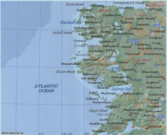
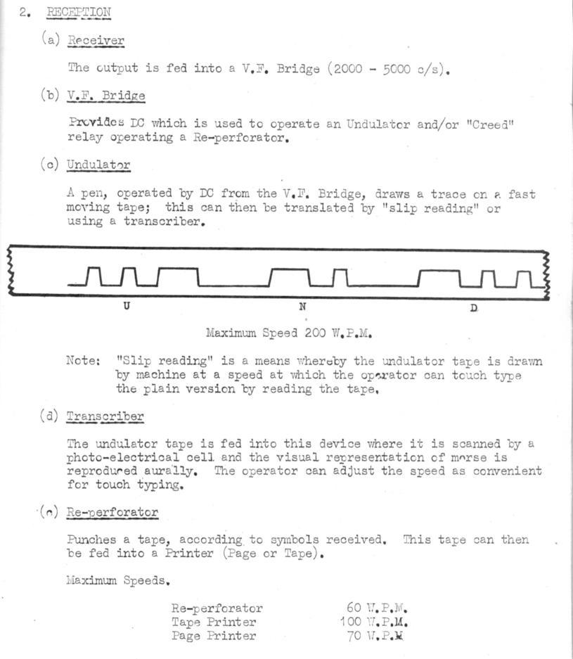
| Wireless Telephony. The De Forest system now in HMS Vernon for further trials. Transmission of voice to ships in Portsmouth Harbour on 20,000 feet (49kHz) using the main aerial were poorly received. (49kHz by today's standards requires not only a very special aerial, electrically if not physically of an enormous length, but also a goodly amount of aerial output power). Trials with HMS Furious out to 10 miles resulted in strong signals with the station at Portland (Dorset) receiving very faint signals: in either case, the spoken words were indistinguishable. This was approximately on the 'T' Tune (234kHz). Blame for failure put down to the Arc transmitter (as opposed to the Spark) and the poor articulation and responsiveness of the microphone. (The navy seems to have a down on the Arc transmitting technology!) The Arc "tends to hiss and to splutter" they say. Burning (coal gas was used) of the Arc necessitated regular re-tuning to keep the primary transmitter circuit in tune with the aerial. A sooty deposit from the flame on the Arc tends to lead to short circuiting. Conclusions after experimentation - "that the system is therefore unreliable at present and unlikely to be of use in the Service." Poulsen's Wireless Telephone. The company working the Poulsen system of telephony have abandoned the use of the Arc transmitter as being impracticable. Wireless Telephone systems used in HMS Good Hope. Trials with a De Forest piece of kit adapted for Service requirements. Some satisfying results but much work needed for improvements. Arc transmitter still a problem. American Systems of Wireless Telephony invented by Mr McCarthy as observed by the British Naval Attach? to Washington. Favourable results but a transmitter is needed to combat heat. Lapel's Wireless System. Visit by RN Officers to a Station site in a field near to Slough. Communications between Slough and Twickenham (12 miles) successfully achieved. Ability to alter the musical Morse code note was demonstrated by being able to play the air God Save The King. Note the coupling - is this a major break through ? The firm proposes to sell two types of their kit -a small set 80-140 miles for ?150 six weeks delivery and a large set, 800 miles (using AC) ?300 and in excess of six weeks delivery. Set are made in Germany but soon in England also. Endurance Test carried out - 100 words to be transmitted at 20 wpm without a break. Message received at a station in Hunstanton (Norfolk) where signal strength dropped during the five minute period from 8 to 5. The same wireless system using Arc and Spark together can be used surgically for cauterisation - stopping bleeding. Navy quite enthusiastic and bought three sets for further naval experiments. Of the bought sets mentioned above, one was fitted in HMS Vernon and one in HMS Furious which was at Portland. DC appeared to be better than AC and gave a good Morse note, and the same strength of signal was received in Furious using both AC and DC. The DC musical Morse note better than the Service MK1* and higher in pitch than Service MkII, and, if loud, better for reading through atmospherics. Service wavelength 'R' to 'W' can be used but range decreases and wavelength increases. Wavelengths shorter than 'R' Tune (380kHz) i.e., above 380kHz in frequency, cannot be used. Range 60 miles on 'S' Tune (298kHz). The Lapel set no good for Service purposes in its present form. No good at all for naval airships and portable/harbour defence sets as was originally hoped for. Recommended further trials to experiment with systems obvious merits. Report on visit to Clifden (Irish shore W/T station). Marconi high power station . Operators are ? mile from actual transmitter. Normal system is employed namely that the operator's Morse key operates a key in the transmitter circuit to send out sparks. Receivers are in the same place as the sending area. Aerial is enormous and will be even larger when finished with 18 tall masts each with a wire approximately ? mile long. Wires on the receiving aerial (above the transmitting aerial) are getting on for one mile long. New revolving spark gap disk of 4' in diameter revolving at 3000 revs per minute - this creates the sparks, and remember that a Morse code single dot (a Short) is represented by a series of many sparks. Receiver uses valves in preference to magnetic detectors. Tungstein is now used instead of carbon for filaments. Duplex Telegraphy - sending on one frequency and receiving on a different frequency between two points which of course requires two aerials. Here we have an incredibly ingenious way to transmit and receive simultaneously with transmitter and receiver aerial being in the same place and with the transmitter radiating a high power signal of tens of kilo Watts. The figures are mind-boggling. The spinning 4' heavy disc with its brass studs (which generate the sparks) allows the receiving circuit (receiver and aerial) to function normally for 0.0047 seconds and then breaks the receiving circuit for 0.0003 secs for a spark - I ask you, who the hell can calculate a time of 0.0003 seconds ?. This means that for all practical purposes the receiver is connected permanently without induced damaging radiations from its near neighbour transmitting aerial. (The very idea of this system was being used certainly up to and including 1980. The Type RIS6 (Radar Interference Suppression) was synchronised with the trigger of the Type 965 Radar with its associated Type AKE aerial. The RIS6 gated output was wired to a switchable unit physically connected inside all Type CUJ UHF Receivers (225-400MHz). When the Type 965 transmitted (25kW on 224MHz) each receivers IF stage was disabled for the duration of the pulse, thereby protecting against a repetitive type of pulse interference. The action and speed of this disabling was so quick that on an analogue voice circuit the users were not aware that this was happening. However, when using digital signalling (coded or on-line voice for secrecy or DLT (data links - computer to computer over UHF) the RIS switch inside the assigned receiver had to be set to off to avoid the crypto data key stream from losing synchronisation because of 'hits'). Note high speed Morse at 100 wpm 100 years ago. Also note in the Fig., the now familiar commutator with its brush gear "with hardly a spark." Marconi tells of the new Tungstein Valves suitable for short wave working. Note traffic levels for a major high power W/T station - 2000 word per day - @ 20wpm, that will take.........?. "As a general rule, if a signal cannot be got through by wireless in three hours, it is sent by cable." Clifden's aerial layout diagram. |
- - - - - - - - - - - - - - - - |
The contents of this file 1909/7 are listed below. |
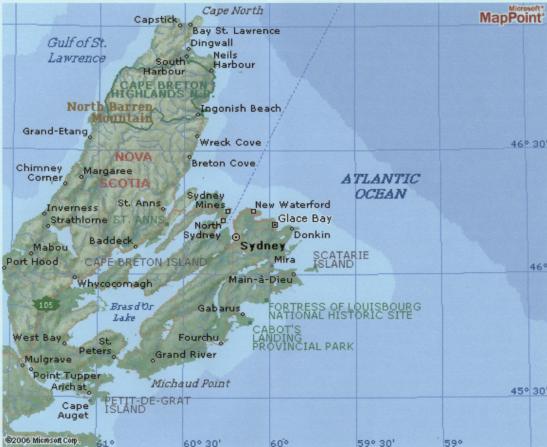
| Where is GLACE BAY? It is in Canada in the Province of Nova Scotia NE of Sydney, not far from Halifax where we British submariners were based on HMS Ambrose in the 1950's and 1960's.
|
- - - - - - - - - - - - - - - - |
The contents of this file 1909/8 are listed below. |
| Information on foreign ships and stations extracted from intercepted signals sent in by the naval shore stations.
|