The contents of this file 1913/1 are listed below. |
Index. List of plates. W/T Appendix - General Summary. Note the irony of the statement that the signal book will be in general use before the 1914 Manoeuvres. 
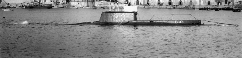
The Mk11 sets converted to Quenched Spark (QS) were subjected to a long distance trials between HMS Vernon and HMS Vindictive. BUT shortly after this event, the navy issued the following statement. In the light of things to come, WW1 in just a few months time, the time was not right for a major swing away from mainstream thought based on a few years of experimentation! The high hopes and thousands of man-hours experimenting and trialling QS have, for the sole reasons of getting more frequencies from the spectrum, been dashed in favour of the Arc and the Continuous Wave transmitter. You will recall just a couple of files ago, that if the navy could have developed a special receiver, the all-invading QS transmitted signal would cause mayhem to the enemy but not to our navy. That is not now to be, and this year, 1913 marks a very important watershed (in historical terms) because it heralded in what today is commonly called Morse Code, A1, CW, A2J, Carrier Keying, Carrier ON-OFF and in other forms MCW (and its variants) and ICW. Surprisingly, Rinella at Malta is still a jury-rig and still cannot transmit on full power. Communications between Malta and Gibraltar and Horsea are satisfactory but not between Rinella and Horsea direct. Now for an all change! We have mentioned repeatedly throughout this early 20th century slot the "Short Distance W/T Installation". As of now, that is to be renamed the "Battleship auxiliary W/T Installation". There will also be a "Cruisers auxiliary W/T Installation". The "Portable and Harbour Defence Sets" continue to give great satisfaction. 1913 sees the expansion of the destroyer installation which is now capable of transmitting on any walvelength between 635 and 2000 feet (1.54MHz to 491kHz). A new W/T organisation due in 1914 when destroyers will be allowed to receive signals direct from high power stations (Malta, Gibraltar, Cleethorpes, Horsea). Destroyer deck insulators (DI) still causing problems. Submarine W/T fits progressing. 'Spec drawn-up for fitting out 'B', 'C', 'D' and 'E' classes as these boats come in for refit into Dockyard hands. On W/T reception in the Fleet, one major problem persists namely that on shocking or de-sensitising receiver detectors when transmitting, such that it takes some time before the receiver recovers and can receive again. There is no detector which will allow a "listen-in" between transmissions of Morse characters. Good progress made in W/T for aircraft/airships. Instructional report - still the Signals officer lags behind the Torpedo officer in numbers trained or in training. HMS Vernon and HMS Defiance figures together show that the overall qualifying numbers for PO Telegraphist (Q) are 48. Notice the introduction of the "tiffy", the artificer, and that 13 warrant officer telegraphist's qualified but only the one got promoted. Telegraphists branch - at last, the 'killicks' have overtaken the PO Telegraphists in numbers. Look at the Boys at sea in 1913. In the period 1914-1918 many of these boys would die, some trained in HMS Ganges and some trained elsewhere like in HMS Impregnable for instance. Jack Cornwell, Victoria Cross, is the most famous Boy Rate to die displaying great bravery and commitment to duty, representing the danger all boys faced and despite their youth and immaturity, they gave their all, poor bairn's. This death rate amongst Boys was repeated in WW2 and in HMS Hood alone, six Boy Communicators (3 Buntings and 3 Sparkers) plus many other Boy Seamen perished, whilst one young Bunting plus two others survived. God rest their Souls. Revision of Signal Books - bewildering in some cases but introduces specific handbooks for the Fleets; for patrol flotillas, and for submarine flotillas. Vocabulary Signal Book to go. A W/T Committee is sitting in the War Office and has decided that the Army should use the Naval W/T procedures. W/T Shore Stations - General - Destroyer bases and their communications needs are well addressed and completed. The much revered DIP (Differential Interference Preventer) is now seldom used. High power stations are doing well in both reception and transmission. Surprisingly QS (quenched spark systems) have been discontinued. Poulsen Arc experiments abound. S.S.G. is the new thing! It stands for Synchronous Spark Gap technology. Transmission tune now in 1913 is a singular event - the primary coil dictating which wavelength is used to transmit on. The new adjustable primary coil with two adjustments (one for 'X' and one for 'Y') will be provided to each high power station. Gibraltar station on the move to a more defendable position. In its new home, one chamber to be for the diesel engines, one for the transmitter and one for the receiver. All three will be in the base of the rock. North Front now a 'Z' Tune stations (70kHz). A new station will be built near Europa Point which will be called "Rock Station" and will take over the duties of Windmill Hill which is to become a Communications Station. In war it will become a naval station and in the meantime, will be manned by naval ratings. Malta - not to be Quenched Spark fitted after all but a bog-standard Spark Transmitter transmitting on 'Y' and 'Z' waves ( 76-70kHz). Malta and the UK communications not good because of atmospherics. Ships in the Mediterranean Fleet out to the East are not well served by Rinella. If Rinella reduces its signal in frequency to a note of 275 c/s, signal can be received loud and clear by night and readable by day. At Alexandria, signals were, to say the least, confusing and complicated. HMS Black Prince reported all signals from all sources weak but that North Front was stronger than Malta and Cleethorpes was heard at times. When signals from Horsea were strong, signals from Malta were weak. Great circle (as opposed to rhumb lines) are the cause of many of the problems experienced in the Eastern Mediterranean. (Ionosphere ?) Spark camera photography approved and equipment issued accordingly. Brown's Telephone Relay - still, after many trials, going through the mill, but it has many problems mutually amplifying signal and noise together. Service Mk11 - still going! Magnetic Keys - Type 1 with a change over switch (COS) followed by Motor Buzzers. The rest covers now well saturated subjects! |
- - - - - - - - - - - - - - - - |
The contents of this file 1913/2 are listed below. |
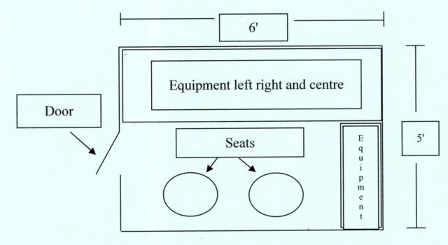
Motor Buzzer - continued from the last file above. Of interest here, is the variation in speed of the Motor's. To get the maximum power output coincident with the highest Morse musical note the Motor had to be run at full speed. For ease of explanation, let's say that full speed = 100 Watts and that the highest Morse note is 1000 c/s. However, by varying the Motor speed two objectives could be achieved; power output and pitch of note. Thus in a harbour (for example) in a training environment we could have three groups of ships each conducting an exercise. Group 'A', the battleships, might run their motor's at ½ speed resulting in a power output of 50 Watts and a Morse note of 500 c/s: Group 'B', the cruisers, at ¾ speed with a 750 c/s note/75 Watt output, and Group 'C', the destroyers using a ¼ speed Motor giving 25 Watts and a low note of 250 c/s. Obviously, all three could operate on the same wavelength each group of operators (as in real life) training their ears/brain/pencil arm to tune-in to their note and tune-out the other two notes as interference - excellent and realistic training. Mk11 sets - spark gaps - trials in HMS Albemarale and HMS Glory 30 miles apart. Alterations of the cooling system for the spark gap. Results look good and HMS Vernon wants to increase the p.s.i. Morse key standardisation - to be a mixture of new keys procured commercially and the old keys to be modified by Portsmouth Yard. Type IV Destroyers set - now fitted into 163 ships. The aerial fits are the weak link and cannot be used on the many different wavelengths soon to be introduced. Major study necessary. Experimenting with different types. 'Nelsonic' Buntings getting in the way of modern technology. No signal halliards to be near W/T wire aerials. W/T Installations in Torpedo Boots (no, not German, but ours mis-spelled or a typo - there are one of two in this file). Poor old seamen! Bet they just loved old sparks. New aerial tuner so that destroyers can tune to all the newly created wavelengths one of them being 1.3MHz (765 feet). Destroyers new 'Protection Switch (our send/receive relay). Earths the aerial input to receiver and also earths the detector stage. Ruby (red) glass device surrounding oscillators and the spark gap allowing one to see the spark whilst giving the spark a safe and near perfect environment (cooling etc) for its high-end efficient needs. Windows in doors of destroyers W/T Office with switch to switch off lights when the door is open? We can't fathom this one. Originally the Office is on the upper deck without any windows of any kind. Because we don't want lights showing at night, when the door is opened a micro-switch is broken putting the lights out, and when shut the lights come back on again that is assuming the main switch is not switched off. Now, a window is to be added to the door and...........? Heavy brushing on a destroyers Deck Insulator (DI) when transmitting on 490kHz. HMS Vernon to the rescue ! Experiments looking for a range of 150 miles on 196kHz from destroyers - Project abandoned. More trials and more modifications. Destroyer Type IV Set - hugely modified went into HMS Velox who was despatched West to Falmouth for trials. Reliable communications achieved out to 80 miles. From Portsmouth to Falmouth (as the crow flies ATCF) is 181 miles: from Portland it is 119 miles and from Devonport (HMS Defiance) it is 44 miles. If HMS Velox was fitted-out by HMS Vernon in Portsmouth (as most trial ships were) she was half way across Lyme Bay (West of Portland) when best communications were achieved, less than half way to Falmouth. HMS Velox' aerial strung between two 60 foot masts 50 foot above the sea, was thought to be capable of a range of 120 miles. Battleships are all fitted with 'Battleship Auxiliary Sets Type III. Some battlecruisers are also fitted. However, when the 'Cruiser Auxiliary Set' is available, battlecruisers will get that set along with all the other cruisers nominated - see lists page 5 of 10. The 'Cruiser Auxiliary Set' with be known as the Type IX set. Problems with the 'Battleship Auxiliary Sets'. The 'Cruiser Auxiliary Set was used for testing QS (quenched spark) but failed and all trials were abandoned. New kit was acquired and tested in the cruisers HMS Achilles and HMS Vindictive. These trials were successful and a purchase was placed for the new Cruiser Auxiliary Set. It is hoped to get a range of 25 miles on a wavelength of 4 or 6.2 LS (2.38MHz to 1.92MHz) and the equipment will have the very first automatic send/receive switch fitted. Diagram/drawings of the Cruiser Set (Fig 6 and Plate II in two parts for ease of copying a large picture) give a good indication of the full transmitter circuit. The tuned circuits (the primary 'E' quite sizable adjustable copper tubes) and the transmitter condensers (those that cause the discharging spark) sitting in a tank filled to the brim with oil, all 25 gallons of it. We will be covering the 1914 version of the Destroyer Type IV Set in full in the transmitter/transceiver section of this site. Looking at page 11 of this file it is of interest to read of the Cruiser Auxiliary W/T Office which is quite separate from the Main W/T Office. This is truly of midget submarine sizes with the complete office measuring just 7' 8" square, the transmitting cage (unmanned) 3' x 4' 8½" and the silent cabinet with the operator, his Morse key and receivers just 4' 8½" square. The scale shown in Fig 8 has been vitiated (copying has destroyed the scale of the original picture) and taken on face value, it measures 6½" representing 7' 8". |
- - - - - - - - - - - - - - - - |
The contents of this file 1913/3 are listed below. |
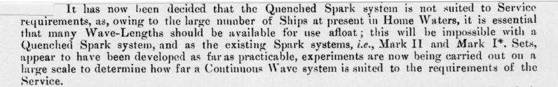
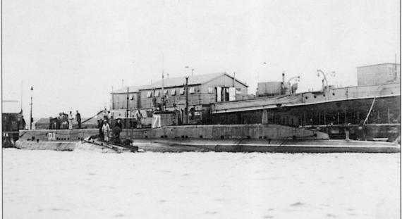
Submarine Fits. Submarine Set Type X= Portable Form, and more or less a modified Type 4 Destroyer Set was fitted to HM Submarine B5 was not suitable for all boats. The system was subsequently much modified (and became the Type 10 proper) to be fitted into Classes B, C, D, E and X. The submarine motor alternator gives 1kW @ 100 c/s 70V RMS. Two versions. One working from 95 to 140 V DC for classes B, D, E and X, and the other from 155 to 200V DC for class C. Can be used at all times when on the surface whether charging main battery or not. The power oscillator tuned circuit will give a maximum of LS21 = 944' = 1.04MHz., (remember the maximum means the longest wave - we would talk about its lowest frequency). Normal Tunes permit the use of Harbour Defence Wave (New Tune C) = 514' = 1.9MHz; Submarine Wave (the forerunner of 4340kHz) (New Tune D) = 635' = 1.55Mhz; Destroyer Wave (New Tune E) = 756' = 1.3MHz. The W/T Office with its traditional Silent Cabinet was quite an affair. Look at Fig 9 for example. Here, the material used is (a) substantial wooden support frame (b) lead (c) canvas (d) felt (e) 5-ply (plywood) (f) sound proofing wood. For the very earliest submarine W/T aerial see the picture in the file. The aerial was functional but as one would expect in those early days cumbersome and inefficient. In the bigger boats, the D and E Classes (this is D1 with a small Holland Boat approaching her portside ballast tanks) the overall aerial height was 35 feet but in a small boats, the B, C and X Classes the aerial was 30 feet (this is the Boat B10 below). Notice on the "Typical Rig" Drawing that the Deck Tube is quite someway aft of the conning tower so this marks out the position of the W/T Office. Also, you will note doted lines on three parts of the casing two forward and one aft. These are the stowage position for each of the three support masts which are drawn upright and operational. It must have been some task lowering these masts at the order 'open up for diving' and fortunately in those days, aeroplanes were not what they were come WW2. However, the text tells us that in many circumstances the Skipper would dive with the aerial still fully rigged and taut and that there were no set procedures or Standing Orders. The turbulence caused by such a large mass of wire aloft would have created some all telling noises plus the very obvious danger of anything snapping and ending up wrapping itself around the screws or hydroplanes. For the two diagrams forming the Type 10 Connections, there is a generous overlap provided in case you want to print both pages and then marry them together for a better view of the system. The idea of HMS Vernon providing telescopic masts was wonderful although two independent masts being raised or lowered with one piece of wire stretched between them might have caused problems with under or over stressed tautness. Before WW1 started, no fewer than 26 British submarines were fitted with W/T with a further two Commonwealth boats of the 'E' Class. In the 1914-1915 financial year there was an ambitious fitting programme planned, and for the future (probably marred by WW 1 although our submarines were not overly involved in the war in any great numbers) where HMS Vernon's intentions were to redesign and fit a W/T Office more in keeping with the hostile environment of submarines operations. Portable and Harbour Defence Sets - issue lists. Instructions in the use of - 3 PO Telegraphists have been added to school' instructional staff to teach a one week course to ratings awaiting a draft to sea. W/T in aircraft. Very important for scouting capabilities. France and Germany use it and the big German airships can communicate to distances of 200 miles and more. H O W E V E R things are not that simple and communicating with aircraft is a science not yet developed to the same degree as that used for communications to and from ships. Read the article to the above. System used! The earth of a ship or a ground station cannot be used in an airship/aircraft. They have to replace this by a 'balanced aerial' which is a massive amount of wire wrapped on a triangular shaped forma placed inside the airship - if you want, it is the braiding of the coaxial cable. In addition, the airship has a normal aerial, in this case trailed from underneath the airship and can be wound in or out accordingly - think of this as the central core or feeder of the coaxial cable. The two aerials together form the airship/seaplane aerial. The amount of wire trailed depends upon the wavelength to be used, and the rule of thumb, is that the trailer should be a quarter of the required wavelength i.e. to use the 1000 foot wave the aerial length should be 250 feet. Of course today, that is second nature to us for an end-fed aerial where we use the sign λ/4. The transmission technology used is for that of a standard rotary spark gap system emitting a 0.25kW musical signal. The seaplane's observer-come-radio operator has a set procedure laid down for him to send a signal which is listed in the file. (See below for next article). New organisation of wavelengths to enable aircraft to co-operate with the Fleet, with Shore Stations and with each other is soon to be issued. 300, 700 and 1400 feet have been experimented with and 2900 feet is to be tried. Advances and improvements to be made in the near future. Air ships. Read the article above. "Gamma", "Parseval" and "Astra Torres", are all names of airships. Under aircraft W/T stations - some of these were Fleet Air Arm sites and some were Royal Flying Corps which became embryonic RAF stations. Notice the mention of Calshott on Southampton Water (River Test) which became a very famous flying-boat station in later years. See the importance of the personnel assigned to W/T in 'flying things'. Quenched Spark (QS) already 'put to bed' as a non-started with CW (Continuous Wave) technology now the 'in' thing. Routine and mundane matters concerning Rigging Insulators, Coils for Emergency Sets, Wavemeters and Receiver circuits. Alterations and amendments to apparatus. Starts at the very end of the file and continues into the next file. |
- - - - - - - - - - - - - - - - |
The contents of this file 1913/4 are listed below. |
First part continues from last file above. Aerial tuner - 21000 feet = 46.78kHz = 10400 LS : wavelength in feet = 206 √LS. Aerial Corrector for use on SIMPLEX circuits - addition of tuned circuit circuitry. When using DUPLEX it will be short circuited. 
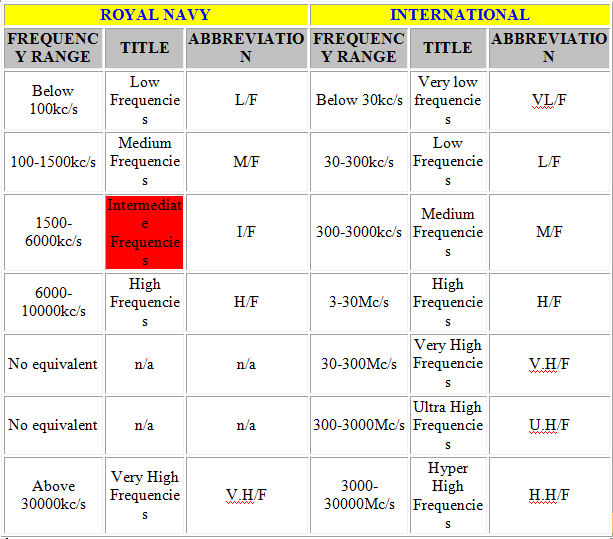
Although a highly detailed and technical paper which I am sure most of you will readily miss, there are a couple of pointers to articles of interest. In the "trials and results" section (page 3) they state two advantages in using the aerial corrector/acceptor namely a gain of 10% in QSA and greatly reduced QRM/QRN. The disadvantage (b) is indicative of either poorly tuned or unstable (wandering) transmitters and/or the TRF receiver where the bandwidth is fixed offering signals on-tune an uninhibited path whilst piling on the dB's of attenuation to those off-tune - no Intermediate Frequency very wide, wide or narrow filters: Intermediate Frequency is stated that way and not simply as IF. In these days, I/F also meant Intermediate Frequency, and although not used internationally, the navy used it as a frequency/wavelength designator. The navy has always used different frequency bands from those used by civilian organisations and their nomenclature was:- In the second paragraph beginning "There are two ways...." we are dying to add 'or by the use of XTAL Oscillators, synthesisers and superhets'.......but of course we can't. Flippant? No. Just trying to make the subject more interesting. Note, dear old HMS Collingwood in one the list of ships nominated to take part in the trials. Detectors and Accessories. Much of it is routine and not for a casual read. However, since we can picture the early W/T operators sitting in their claustrophobic boxes, the sizes of the standardised silent cabinets should be of interest. As a general rule, the big and mighty ship's had a Mk11/Mk11* installation and with it came a large/double cabinet measuring 5' x 6' x 6' 9" which was the maximum height although in many cases actually lower. To get a good idea of what it must have been like, first print the diagram which you will find on page 5 of the file. Fold your printed page on the two vertical lines shown so that you have a left hand side, a front of cabinet side and a right hand side, and then stand the resultant shape on your table. It won't be symmetrical because on the end of the left hand wing is the cabinet door and the back of the cabinet is immediately behind the two seats - see also our drawing here. Have a peep inside your folded page to see a typical pre-WW1 SILENT CABINET and thus into roughly half a W/T office where the transmission kit is not shown. In actual feet per man, each man has less or the same as the submariner. For a smaller ship, a cruiser with Mk1* for example, the size is 4' x 3' 9" x 6' 9" max; a destroyer the same size give or take a whisker. Battleship/cruiser Auxiliary cabinets 4' x 4' x 6' 9"; submarines 3' x 3' x 5'. The notes on Plates Nos VII and VIII are no longer relevant. Just Plate VII (although not named as such) is shown, and in place of Plate VIII, we has shown our picture above. Tuned Testing Buzzer - Marconi kit - unsuccessful trials aborted - back to old system! Transmission of messages in HM Ships - rather surprisingly at this point in late 1913, the internal communications in British warships was not standardised, and as you can read, there is pre-warning that in the future, they will be. Detector and Protecting Switch - subject already well covered, although there are small alterations mentioned. |
- - - - - - - - - - - - - - - - |
The contents of this file 1913 Aerial Flown from Kites are listed below. |
This is a good exercise in understanding wavelengths, quarter-wavelengths and LS (tuned circuit values) with a quick reference to the capacity of an aerial. At this time their symbols were very different from ours and whilst we have regularly mentioned things like 'jars' 'mics' 'LS' all now long gone measurements, we need to mention measurements still used/required but with different symbols. The symbol for Curve II is denoting the capacity of the aerial. This total capacity is the sum of all capacitances in the aerial in parallel with each other (caused by natural phenomena like the earth's surface for example and upper deck chunks of metal) and is measured on a wavemeter. The measurement is still relevant in some forms of aerial but is no longer a stand-alone measurement criterion. Although we have used the symbol λ (lambda) throughout these early W/T files to indicate wavelength to avoid confusion, in truth that was not the case at this time because λ was used for 'virtual inductance of an aerial', the capital letter 'Y' being used for wavelength. We have already mentioned that the letter 'R' 'V' and 'L' (meaning resistance (ohms), volts and Henries (inductance) were the same then as now, with the letter 'C' = Amps, the letter 'S' = Farads and the letter 'Q' = coulombs, where of course we use the letter 'I' for current and 'A' for amps, the letter 'F' for Farads and 'C' for capacitance, using the letter 'Q' as a reference to a circuit.......'the Q of a circuit is........ Returning to the graph and ignoring Curve II, we can deduce three quite separate things mentioned above. Take for example the frequency 280kHz (not shown on the graph). Look at Curve III and to the left side graduations representing 3500. Following that cross-point down until you reach Curve I and then look over to the right graduations. You should have read-off 280 LS and remembering that |
- - - - - - - - - - - - - - - - |
The contents of this file Commander Silver Top's visit are listed below. |
Oberlaa is just outside Vienna the Capital of Austria. Very impressive results from German built equipment. Wavelengths from 5000 to 20000 feet (196.5kHz to 49.12kHz), day ranges 960 miles overland to 1500 miles at night. 60 wpm MINIMUM SPEED OF MORSE! 1 year guarantee on parts and labour (first time we have seen that actually written down in a contract). The object is for Oberlaa (Vienna and AustroHungarian Empire Capital) to communicate will all its fortified posts throughout its Empire. Can you imagine just how 'red hot' those operators Morse keys would have been when the news of the assassination of the ArchDuke Franz Ferdinand in Serajevo came through, and this not that many months after this recorded visit ? 
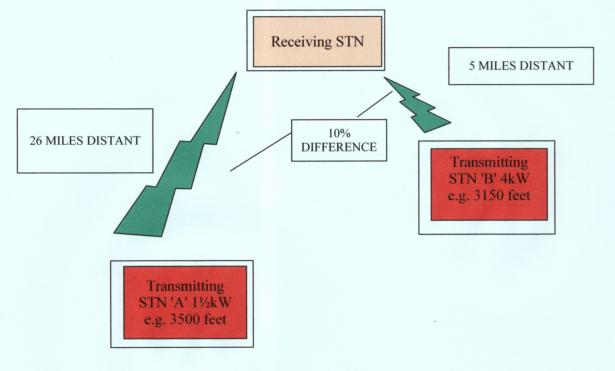
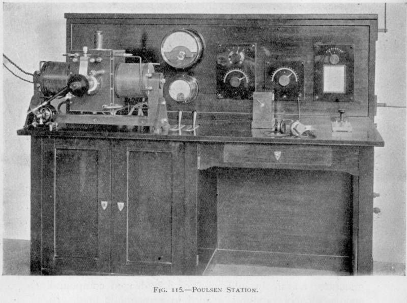
The Austrians had fully adopted the Poulsen Arc transmitting system for all Government Stations and the War Office in Vienna, but their kit was no better than ours which was being tested back in HMS Vernon. The hissing of the Arc transmitter (as previously mentioned by us on these pages) was a major disadvantage of the system and the more power used and the closer one got to the transmitter the greater the problem. Here though they managed to prove by experimentation that the hissing effect could be minimised although they don't say how. Then, OMINOUSLY ? You bet! With just a few months to go before the outbreak of world war this visiting Royal Naval Officer started to get the picture ! A 30000 foot wave was very long indeed (32.7 kHz), and as the article suggests, to 'kick' that around as a ground hugging wave, you need lots and lots of power. Without power, it is rapidly and severely attenuated. |
- - - - - - - - - - - - - - - - |
The contents of this file Goldschmidt HF Alternator are listed below. |
Goldschmidt HF Alternator. Remember, high frequency to them was anything you couldn't hear, RF to us, but in any event, anything above 15 kHz, though the longest wave ever recorded/reached in these years was in the high 30kHz area of the spectrum. This is not a document to read when your head is on the pillow - we guarantee that it won't send you off....! This system, which we saw much earlier on in these pages, is an alternator (AC Device) ready for connection to an aerial system which radiates on a frequency of 46 kHz and can be keyed with a Morse key producing a well defined and pure musical note. This is what this chunk of metal looked like and all just a send an ETA message ! AC Device - use your zooming tool to crawl over this monster. On first learning about it (some time ago) the navy weren't too sure. On a second read (although they haven't said so) they appear still to be unsure of its merits as a Service transmitter. |
- - - - - - - - - - - - - - - - |
The contents of this file HMS Euryalus trials are listed below. |
HMS Euryalus, a four-funnelled cruiser, flying the Flag of the "Umpire-in-Chief" for Fleet manoeuvres had the very first rig to be able to man 3 separate frequencies simultaneously, although she could either listen or transmit meaning that if the frequencies were nominated ABC, then when there was a requirement to transmit on A the operators listening on B and C lost their messages. The best way to understand this simple and illuminating file is to open it and the go to page 3. There you will see her 2 massive aerials (remember they are multi-stranded) with getting on for a mile of wire up aloft, RED and BLUE with a third (still a lot of wire in it) coloured YELLOW which is referred to as the Admiralty aerial which is a vertical aerial hoisted aloft on a halliard. Page 3 also shows the two wireless offices (the proper ships office and a hastily rigged dockyard office close by) in which sat the umpires one listening to the wavelength being used by ships of the RED force 'W' Tune, one listening to 'S' Tune used by the opposing ships in BLUE force and one listening to 'X' Tune for the destroyers and emergency use. The BLUE umpire and the SAFETY umpire sat in the same office. Remember that you are looking at Silent Cabinets where receiving equipment, a Morse key and the operators sat: no transmission equipment of any sort in these places. Much was learnt about the interaction of each aerial on the others which would be useful in the coming months, as more and more ships broke loose from the shackle of being able to transmit and receive on one frequency only without having to engage in a cumbersome change-over of circuitry. Under the first mention of aerial (and thinking about the file above Goldschmidt) note the entry. meaning "virtual aerial inductance times aerial capacity = 112 and aerial capacity (alone) = 1.84 jars." It doesn't matter what the figures mean or even the hieroglyphics for that matter, but that the sign λ was not used for wavelength in those days. |
- - - - - - - - - - - - - - - - |
The contents of this file International Time Signals are listed below. |
The introduction of Radio Time Signals and note that there are no British Stations. Fancy also seeing Timbuctoo of all places, in Africa, but no longer spelt that way. Timbuktu is in Mali on the River Niger. It is roughly 1000 miles east of the Port of Dakar which is in Senegal on the West Coast of Africa. Note the wavelength used for all stations (2500 metres = 8204 feet = 120kHz) and the time signals were made twice a day at midnight and at 10am (the international twenty four hour clock had not yet been established). The time signals used the Morse letters 'X' 'N' and 'G' plus three dashes (longs) at the end of the minute as clearly shown in the diagram within the file. |
- - - - - - - - - - - - - - - - |
The contents of this file Orders affecting Wireless Telegraphy are listed below. |
Some of these titles alone make interesting reading. Look for example at Admiralty Circular Letters (Non Confidential) PERSONNEL near to the bottom of page 1, and to N4407 31 July 1908 (which we passed five years ago in this record) where signalmen from the V/S department were trained to assist in the W/T office. In our days, the MSO was usually in the W/T office (MCO) and was always manned by buntings with the Yeoman of Signals fully in charge. Look at N.12331 of the 12th May 1911 "Ability on Parchment Certificate" which we all knew as Satisfactory, Superior or Exceptional (also, walks on water) and always preceded by the Character assessment of VG (Very Good) and rarely (though occasionally) never less ! Other abbreviations of interest. On page 2 No 756 T.5454 'WT in R.I.M.S. etc' - meant Royal Indian Marine Service which later became the Royal Indian Navy (RIN). Also on page 2 under PERSONNEL, is the 1909 entry No 28 talking about the operating signal ZBM2, which meant put a competent operator on this circuit - the ultimate peer group insult? Many of the other entries in this section are of interest especially the 'coal ship perk' a telegraphist received - we wonder why?. Note the start of the end of the Gunners 'T' and 'G' trained in W/T! |
- - - - - - - - - - - - - - - - |
The contents of this file Poulson Experiments are listed below. |
Poulsens Experiments (been going on for years). Arlington (Washington DC) to North Front Gibraltar, as the crow flies 6000km (3728 miles) but by great circle route further or course. Once again, the promise that the navy will be getting the Arc system. Various reasons as to why the Arc is now more reliable. Range and wavelength - with Arc and the current ships aerials, radiation of wavelengths are from 1800' to 18000' (545.84kHz to 54.51kHz). Using Horsea Island aerial the longest wave yet achieved with the Arc transmitter is 80000LS = 16.8 kHz (Rugby callsign GBR used to transmit a VLF Broadcast to British submarines on 16kHz). 
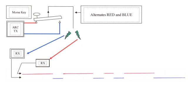
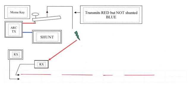
You will recall from our previous explanation of the Arc (see 1907.10.pdf) that it can be thought of as FST Morse where two frequencies are radiated, the FORWARD (or Front Wave) when the Morse key is pressed and the REVERSE (or Back Wave) when the key is not pressed. The receiver is of course tuned to the Front Wave. In this little picture, we show the effect in the ether for both Transmission and Reception for the sending of the Morse letter 'Q'. Here we have an Arc transmitter (the Arc burns continuously like an candle would) crudely connected to a Morse Key the bar of which is the aerial. When sending Morse symbols the RED line (FRONT WAVE) is operative and when not, the BLUE line (BACK WAVE) is. Below, we show two receivers and their respective aerials, the BLUE picking off the 'between key frequency' - the BACK waves- and the RED, the FRONT waves, the proper keyed Morse Code. In the bottom table purposely barely discernable there are two rows each with sixteen columns. Sixteen represents the number of basic time elements in the transmission of the letter 'Q' where each DASH is 3 elements long, the gaps in between characters 1 element, and the DOT also 1 element and, after the 'Q' has been sent a wait of 3 elements before the next character is transmitted: obviously, if no more characters are transmitted then the BACK WAVE radiates a continuous SPACE - no, we haven't got that wrong, although to us a continuous tone would be called a Mark, but read on! Thus, the RED RECEIVER receives the letter 'Q' and the the BLUE RECEIVER receivers the letters 'E' 'I' and 'T'. They are hoping to attenuated the BACK WAVE completely by SHUNTING it to a point where the Arc remains lit to maintain continuous oscillations, but doesn't radiate from the aerial. This little picture gives an idea of what the system will look like when a shunt is in circuit. This will be true CW (Continuous Wave) where the Arc burns continuously giving out an oscillation on the desired frequency with the Morse key providing a conduit for the oscillation to reach the aerial and the ether. Reception of CW (Continuous Wave) This period saw the Heterodyne receiving apparatus for the first time, which was a major break through in W/T and first used by the USN patented by a USA company. The cruiser USS Salem fitted with an Arc transmitter and a heterodyne receiver conducted trials from North Front in Gibraltar to Washington DC USA. Before we look a little closer at these early days of heterodyning, let us quickly cover the salient points of the system. The reception of Continuous Waves (which are undamped waves) in an aerial differs from the receipt of Damped Waves from a spark transmitter. Damped waves arrive in the aerial one train at a time separated by comparatively long periods (see this file Spark Photography). This allows the earphones condenser to discharge through the earphone during each train thus resulting in a change of current for each train of waves. If these follow each other at a regular time then a note is heard in the earphones corresponding to the repetitiveness (frequency is a better word but it might confuse matters if used here) at which the wave trains arrive. With continuous waves, the waves do not occur in separate trains but as one continuous train during the whole time that the Morse key of the transmitting station is pressed. Therefore, in order that the earphones may appreciate the passing of one long train of oscillations it is necessary to break up that long train into groups succeeding each other at intervals corresponding to an audible frequency. Once done, the earphones will respond to the current due to each group. If the groups are at regular intervals a note will be heard but if they occur at irregular intervals only noise will be heard. Before heterodyning was invented, there were a couple of ways to achieve this and at one stage, the Royal Navy got pretty close to discovering heterodyning. However they experimented with Quench Sparking stating that since the quench spark transmitter caused much interference in the ether, all that was needed was a special receiver (which the enemy didn't have) and all would be well for the RN. If you recall, that idea was dropped as was the use of the Arc transmitter. See file Quenching & Arc Transmitter. We will ignore what those other systems mentioned above did to detect and listen to undamped waves, and concentrate fully on the heterodyne. With the heterodyne method of reception a continuous wave generator of very low power is arranged at the receiving station to generate oscillations in a circuit loosely coupled to the receiving circuit and tuned to a slightly different wave to that of the signal being received. Thus the receiving circuit is affected by two sets of oscillations, those caused by the signal being received and also those caused by the heterodyne oscillator. Today, we take heterodyning (double and quadruple etc., super heterodyning) as routine but this, back in 1913, was heady stuff. If asked today to produce a block diagram of a typical superhet receiver we would expect to see something like this. But way back it was very different. The following drawing looks at the different stages of their heterodyning a la 1913 and after it we will briefly discuss what they got from their system. Line 'A' shows the oscillatory voltage which reaches the detector corresponding to single pressure on the Morse key at the distant transmitting station. Line 'B' shows the resultant DC voltage through the earphones. This voltage is constant throughout the greater part of the signal and would give rise to movements of the earphone diaphragm and therefore to audible sounds at the beginning and end of the signal only. Line 'C' and 'D' show similar curves for the heterodyning oscillator which we call the local oscillator. Note that in 'C' its period and frequency differ from those incoming waves ('A') by one part in five, but that is only to exaggerate the picture for reasons of explanation only. In practice one part in fifty would be the norm. The effect of the oscillations from 'C' alone on the earphone circuit is to cause a steady flow of current and no movement of the diaphragm. Comparing 'A' and 'C' it will be seen that owing to the difference in frequency of the two waves, a length of time equal to five periods of the incoming wave is just enough for the waves to pass from being out of step with one another into step and out again. Now let us consider Lines 'E' and 'F'. Line 'E' shows the result of their passing in and out of step as far as the oscillatory voltage is concerned. The voltage at any moment has been obtained by adding the voltage due to each of the two waves at that moment. The effect of the two voltages combined thus cause regular fluctuations of the amplitude of the combined wave which are known as 'beats'. The period and frequency of these fluctuations are known as the beat period and the beat frequency (hence BFO - beat frequency oscillator). The beat period is the time taken for the two waves to return to the same step and is here equal to five of the periods of the incoming signal ('A'). If the waves had differed in frequency by one part in fifty the beat period would have covered fifty of the periods of the incoming wave. Line 'F' shows the effect of the presence of beats on the earphone current. The current fluctuates at the beat frequency, being smallest when the waves are out of step and largest when they are in step. The earphone diaphragm moves in unison with these fluctuations and the final result of the combination is a musical note in the earphones whose frequency is equal to the difference of the frequencies of the two high frequency waves. This note is called the beat note. The drawing below gives a good representation of the block diagram. The heterodyning frequency (27.2kHz to 428kHz) can be either above or below the incoming frequency. Washington transmitted a prolonged letter 'D' alternately at different times per day first using a Spark transmitter on 78.9kHZ and then an Arc transmitter on 73.17kHz Back Wave when Morse key is NOT pressed and 76.92kHz Front Wave when the Morse key WAS pressed. Thus, the receiver circuitry to the left was tuned to receive 76.92kHz when receiving the Arc. To listening to a musical Morse code note of say 1000 beats (1kHz) one would need to alter the low power oscillator controls to either 77.92kHz or to 75.92kHz: either setting would produce the required note. However, the necessary distance between the receiving equipment and the two heterodyning boxes meant that a second operator was required to adjust the heterodyning settings. The USS Salem could read the Arc/heterodyning out to 2600 miles whereas with the Spark/tikker to 1600 miles. Atmospherics could be much reduced by the heterodyne especially when it is tuned to a very high piping Morse code note. With may permutations of wavelength available, it is possible to eliminate interference altogether or to separate and make the interference a low Morse note and the wanted signal a high Morse note. It was even possible to transmit a signal which only a heterodyne receiver could understand. After Salem's return home, the RN built their own version of a heterodyne which is shown in the file on page 3 of 4. Note that they have encapsulated both the Arc burning box and the variable condenser/coupling coil (low power oscillator controls and circuitry in the drawing above) into brass boxes (respectively 'I' and 'J' on their drawing) each one well earthed as emphasised. Note also that the radiating Arc (from box 'I' via external cables into box 'J') culminates with a coil and a little sliding door to allow the operator access for adjustments. Immediately outside box 'J' is the aerial pick-up which is shown as the aerial loop in the drawing above. This external coil (loop) ('K' on their drawing) in the aerial picks up the Arc transmission and adds it to the incoming signal - the diagram does not show the aerial path to the receiver proper. This is an excellent example of loose or very loose coupling when physically the coils do not touch each other: think of a receiver, any receiver, and when the bandwidth switch is at its widest, say, for receiving A3 DSB Voice then it is TIGHT COUPLING, and when at its narrowest for receiving A1 CW it is LOOSE COUPLING. These two earthed brass boxes could be placed nearer to the receiving equipment where one operator only was needed. Although not mentioned and probably not even known about, this heterodyne oscillator may have also radiated on the aerial itself as an outgoing signal. Many years later, with a comparable system (though with valves and not Arcs) the American Type TCS Transmitter/Receiver was a known source of danger to actually breaking radio silence involuntary. The local oscillator (heterodyne) of the receiver was found to be radiating a goodly sized signal back through the send/receive switch and onto the aerial, which could of course offer a good signal for D/F purposes. The receiver had to be disabled. Also, the theory of the BBC Television van looking for un-licensed television receivers uses this principle. And finally on this subject of the Arc, by 1917 the Poulsen Arc transmitter was as in the circuit diagram below. By this time, two phrases which have figured on a daily basis in the RN since the late 1950's/early 1960's had been coined (or established) and these were 'marks/spaces' and 'frequency separation'. Both related to the transmission of an Arc wave. The first (marks and spaces) replaced the names much used in earlier years of the Front Wave/Back Wave, where, as we have seen, pressing the Morse key sent the Front Wave and releasing the pressure on the key, sent the Back Wave. Now the Front Wave was to be known as the MARKING WAVE and the Back Wave the SPACING WAVE the receiver being tuned to the Marking Wave or as it became to the Mark. To avoid the distant receiver picking up both Mark and Space, it was decreed that a 10% difference between these two radiations was ample to avoid confusion at the receiving end - this established an engineered freqsep. In the example above, Arlington (Washington DC) used 73.17kHz for its Space and 76.92kHz for its Mark, a freqsep of approximately 5%. In the picture below, the Arc is formed over 'Cu +ve & C-ve' and when the Morse key is in its rest position, the Arc travels through the Spacing Coil and onto the aerial: the coil changes the frequency down by 3.75kHz. When the Morse key is pressed the spacing coil is short circuited (by-passed) effectively changing the frequency up by 3.75kHz. This is a picture of a Poulsen transmitting station. Note the Morse key and the headphones on the bench over to the right. |
- - - - - - - - - - - - - - - - |
The contents of this file Reports of Clifden are listed below. |
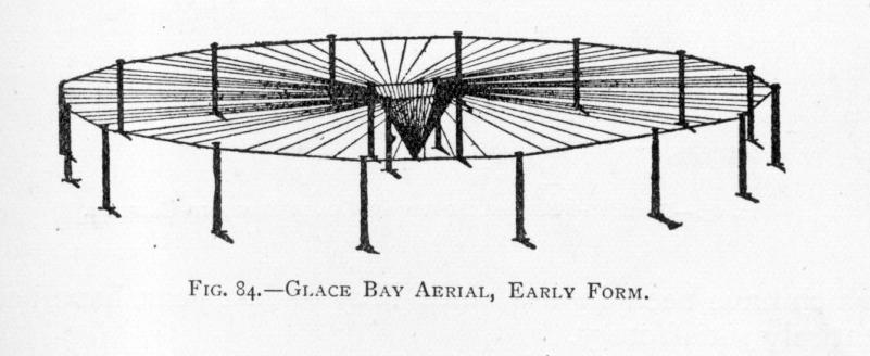
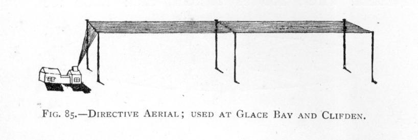
Report on Clifden W/T station. These are some of the aerial used at Glace Bay. Under 1, note the 50 candle power lamp in the aerial circuit. Just as we did in submarines many years later, they would have tuned for maximum brilliance. The charging of the main condenser is quite stunning really - 14600 volts @ 16 amps! Under 2 but ignoring the small continuous wave transmitter, the large set is an attempt to create what Professor Poulsen has already created (continuous wave) but in a much more convoluted way. However, Clifden have experience trouble and things are not going well - but they are for friend Poulsen! HMS Vernon could pick up Clifden using an Arc heterodyne but not without one. Oscillations were continuous but varied in amplitude. The Morse note was dis-similar to that produced on an Arc transmitter. Signals are said to be easily readable across the Atlantic at Glace Bay. Clifden's wavelength was 19550 feet = 50.25kHz. Details about the receiver used and the Lieben valve amplifier/carborundum crystal detector. High speed Morse trial at 50 wpm across the Atlantic was affected by bad atmospherics with several words missed. These missed words were called either "strays" or "X's" by the commercial world but not by the Royal Navy. Trial results vague. Letterfrack Station - aerials and their efficiency and performance vis-à-vis Clifden (close by) and Glace Bay the other side of the Atlantic. |
- - - - - - - - - - - - - - - - |
The contents of this file Vielton Systm of W.T are listed below. |
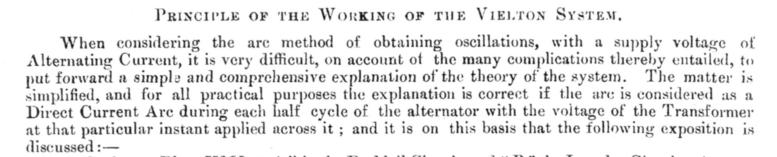
The Vielton System of W/T. The Admiralty recently purchased a Vielton system from the Lorenz Company. This Company has bought ALL the Poulsen and SOME of the Telefunken patents. 
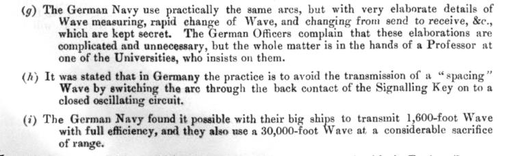
They have supplied the German Navy and Military Authorities with W/T sets based on the Vielton principle. Several sets are also fitted in German merchant ships. So, Germany went to war using the Vielton ! First we want you to read the above. In one, it is anything but simple, so if you are at all interested then please open the file and read on. It is an Arc system with a spark gap for its 'heart'. It is said that the Morse note (which could be varied) rendered them (the sets) somewhat distinctive: good way of knowing when the enemy is around if not practicing radio silence. It was also said that the sets worked well achieving a day time range of 600 miles and that it was possible to put 2.5 to 3kW into the aerial. The set transmits on three frequencies (427.17kHz, 299.54kHz and 200.51kHz - via three position switch) but with circuitry changes can transmit on all wavelengths. Its receiving circuit can receive waves from 1.07MHz to 57.79kHz via a four position range switch. It had a manual send/receive switch, a keyboard on which could be selected a change of inductance and thus a change of note, an almost conventional Morse key circuit routing DC (the operator having first made the 80V DC double pole switch) to the magnetic key and thus to the primary of the main transformer. The heavy font print 'A' and 'B' belong respectively to the Duddel Circuit Inductance and to 'L2', the Impulse Circuit main inductance coil. The three position wave switch affects 'L2' and the main aerial coils also. |