PROJECT UNDULATOR
The Restoration of a 1870s GNT309 Undulator
Written by Andrew Sinclair/Ken Sutton
©RN Communications Branch Museum/Library(Click on an image to enlarge)
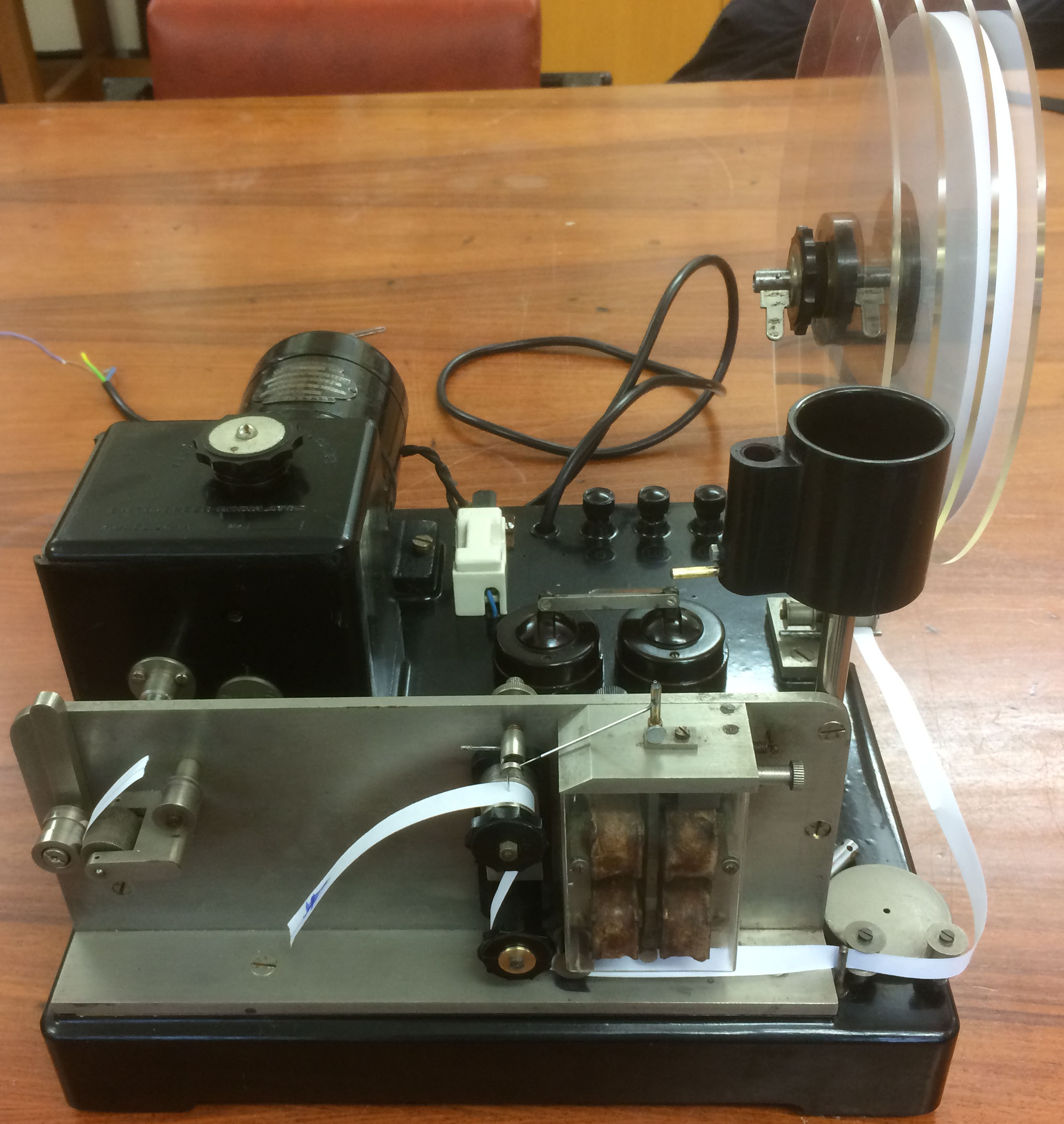
In February 2023 the Royal Signals Museum, Blandford kindly donated a Great Northern Telegraph (GNT) Company Undulator Model 309, This model was designed by GNT circa mid 1870s (this undulator is believed to have been manufactured circa 1920s) and was used to receive high speed Morse via radio and telegraph lines. An Undulator shouldn't be confused with an Inker. Inkers draw dots and dashes on a slim gummed paper tape whilst Undulators keep a pen in contact with the tape and deflect the pen to the side with the signal producing undulations of signal dependent amplitude. They're reckoned to be better suited to subtle interpretation than all-or-nothing inkers..
Normally when starting a project we first of all search and collect any information regarding the equipment being restored. At first we could find no information on this piece of equipment but we did find in the NMRN library a small booklet on the Model GNT 310 Undulator. Models 309 and 310 are very similar in operation and the details provided in the GNT 310 booklet were invaluable in refurbishing the GNT 309. With the kind permission of the GN Company, GN Store Nord, the Model GNT 310 booklet is produced here - GNT 310
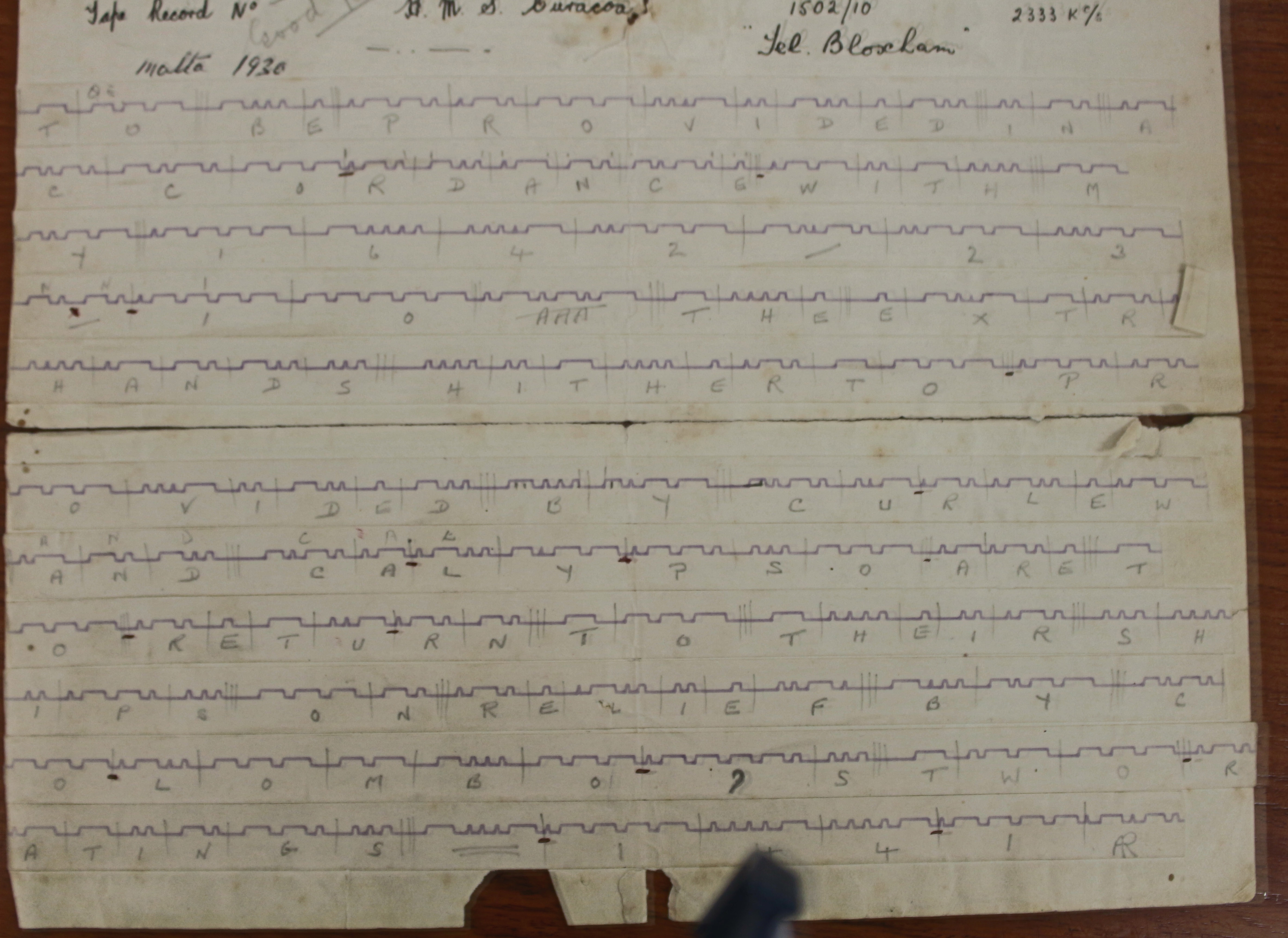
The purpose of the undulator was to receive a Morse signal and then transcribe it onto a paper tape in the form of a square wave pattern. The next two images have been scanned from a real time message received onboard HMS Curacao from the Malta Broadcast on 2333kHz circa 1925. For the uninitiated, the Morse for the letter B is dah dit dit dit which would appear on the 'slip' tape as:
Once the whole message had been received it was then passed to a 'slip' reader, the 'slip' being the whole message printed onto the tape. The 'slip' reader would then slice up the tape and stick it down to a message pad. Once stuck down the 'slip' reader would read the Morse symbols and annotate each symbol with the letter/figure sent. For example:

Restoration:
On receipt of the undulator a thorough inspection was made of the state of the machine with a view to assessing the work required to bring it back to a working condition. The spares compartment contained a spare pen and some lengths of brass wire used to rod out the pens. On first inspection it was obvious that the machine had been stored for a long time in damp conditions and there was a great deal of rust covering various parts.
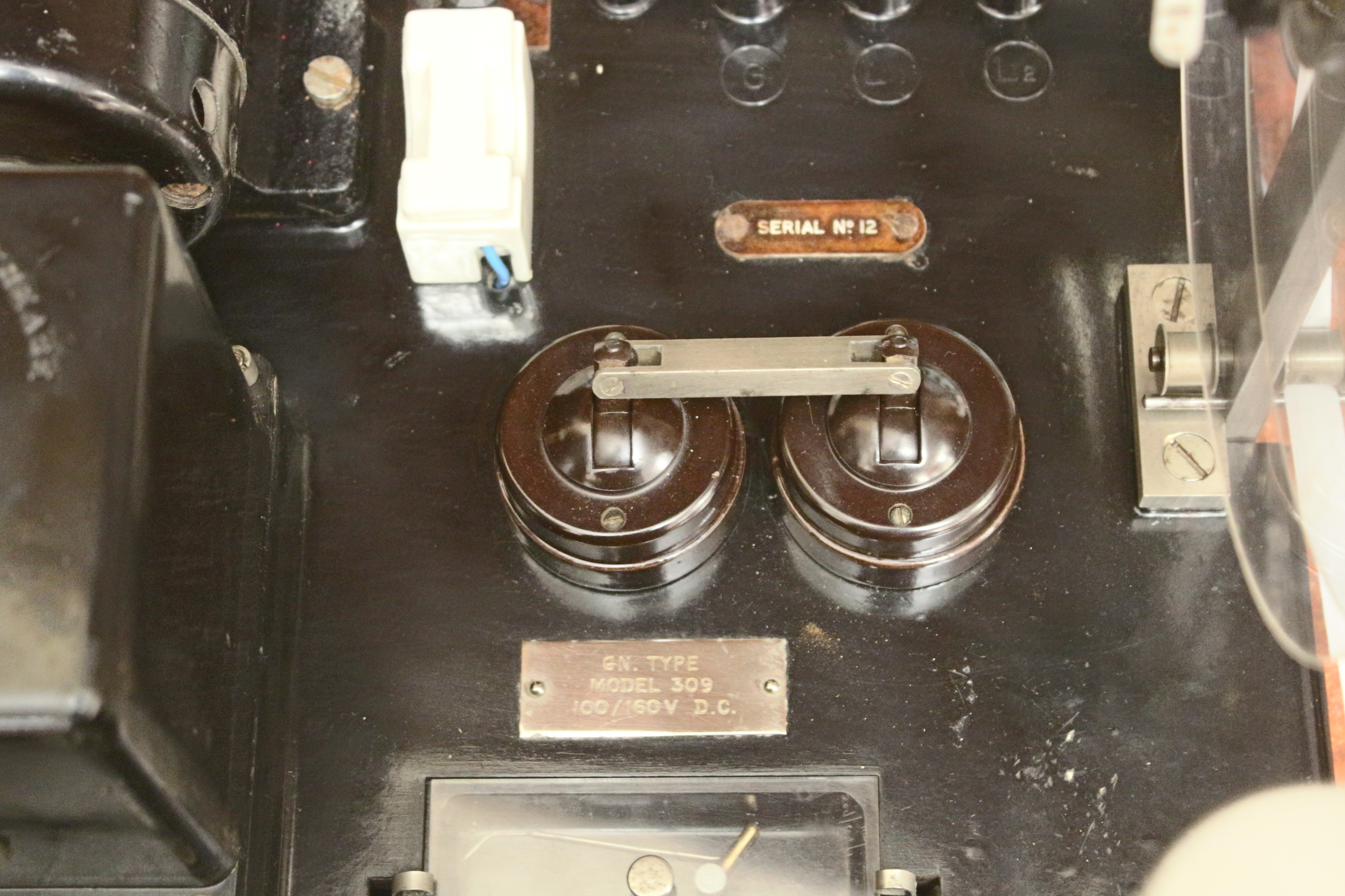
During the rust removal phase of the work it became obvious that the electrical wiring and various electrical parts were either missing or in a very bad state. To this end the whole of the wiring was renewed and wax/paper filter capacitors were replaced with 630V rated polyester. These are not class X/Y as the unit is not mains powered.
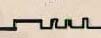
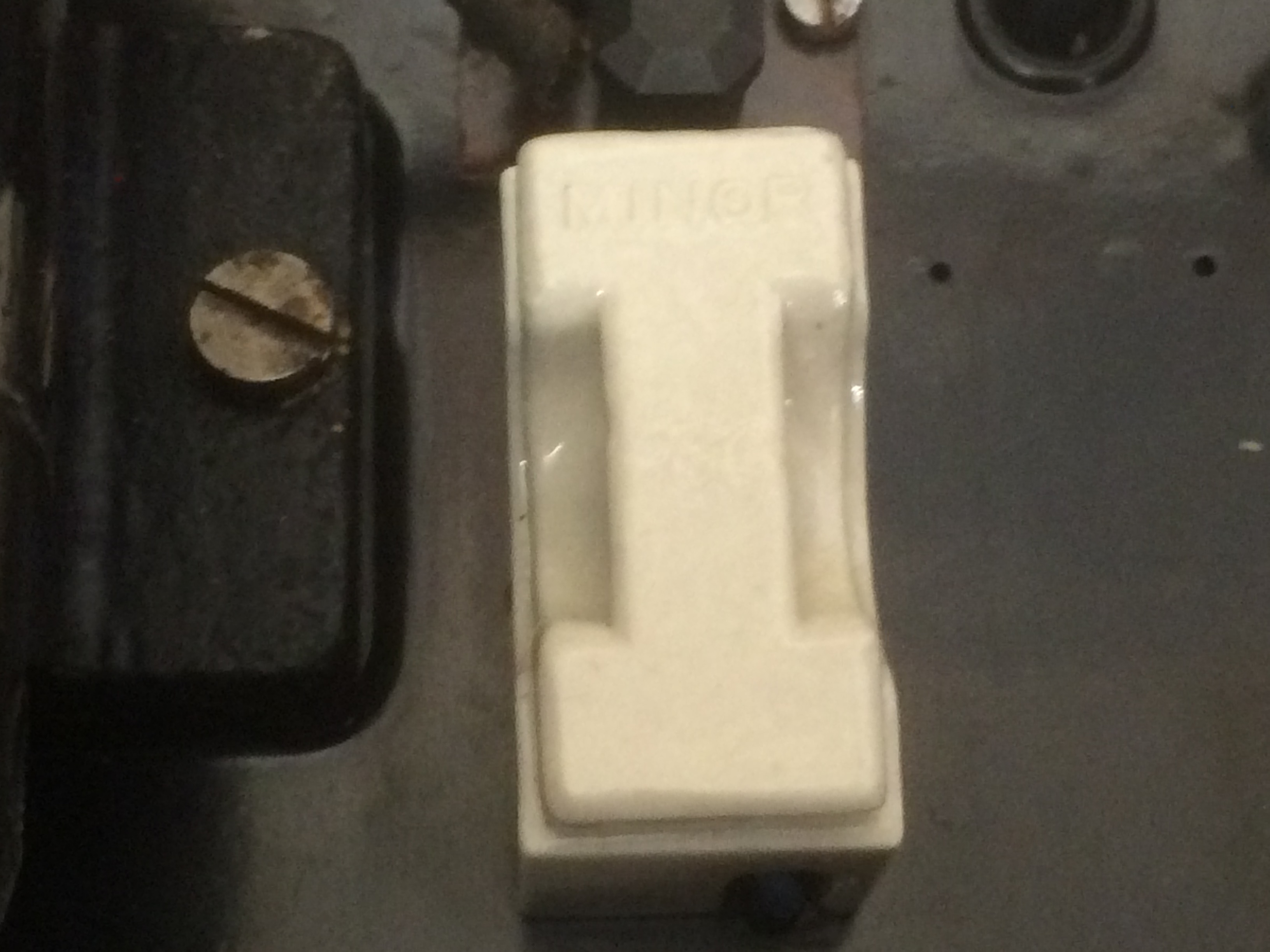
Two Crabtree domestic lighting switches are ganged together with a metal bar. One switch was missing and was replaced with one from a scrap GNT unit in stores. The original switch had three wire connections, and was used to switch the undulator coils on/off. It is believed that it connected L1 to G when off. The new switch is single pole and just disconnects the coils.
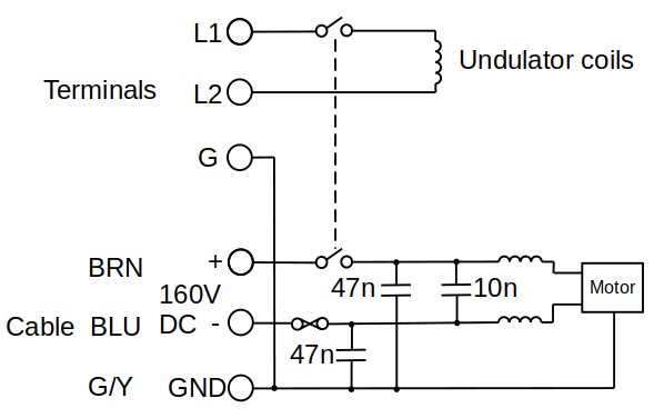
The next stage was to focus on the moving parts. The motor runs from 160V DC, a standard voltage in telegraph offices which had +/- 80V for teleprinter signalling. Many screws were seized and had to be drilled out. Some bearings were rusted solid. One ball race in the speed regulator was so corroded it fell apart! This was replaced with a new R3.5 inch diameter bearing from BRT bearings in Segensworth. Screw sizes used are BA, but there are some odd size ones, such as 7BA.
The pen armature return spring crumbled to dust when touched. A new collar was made from brass and a 0.2mm brass shim was used as a new spring. The motor was cleaned out. It had very heavy white mould deposits looking like cotton wool. The insulation resistance was measured as 10M ohms at 500V. Further cleaning of the commutator end of the armature and the paxolin plate holding the brushes gave a considerable improvement. The insulation is now higher than we can measure. The cork pad in the speed regulator was found to be glued to its disk with Gorilla impact adhesive. It may not originally have been glued?
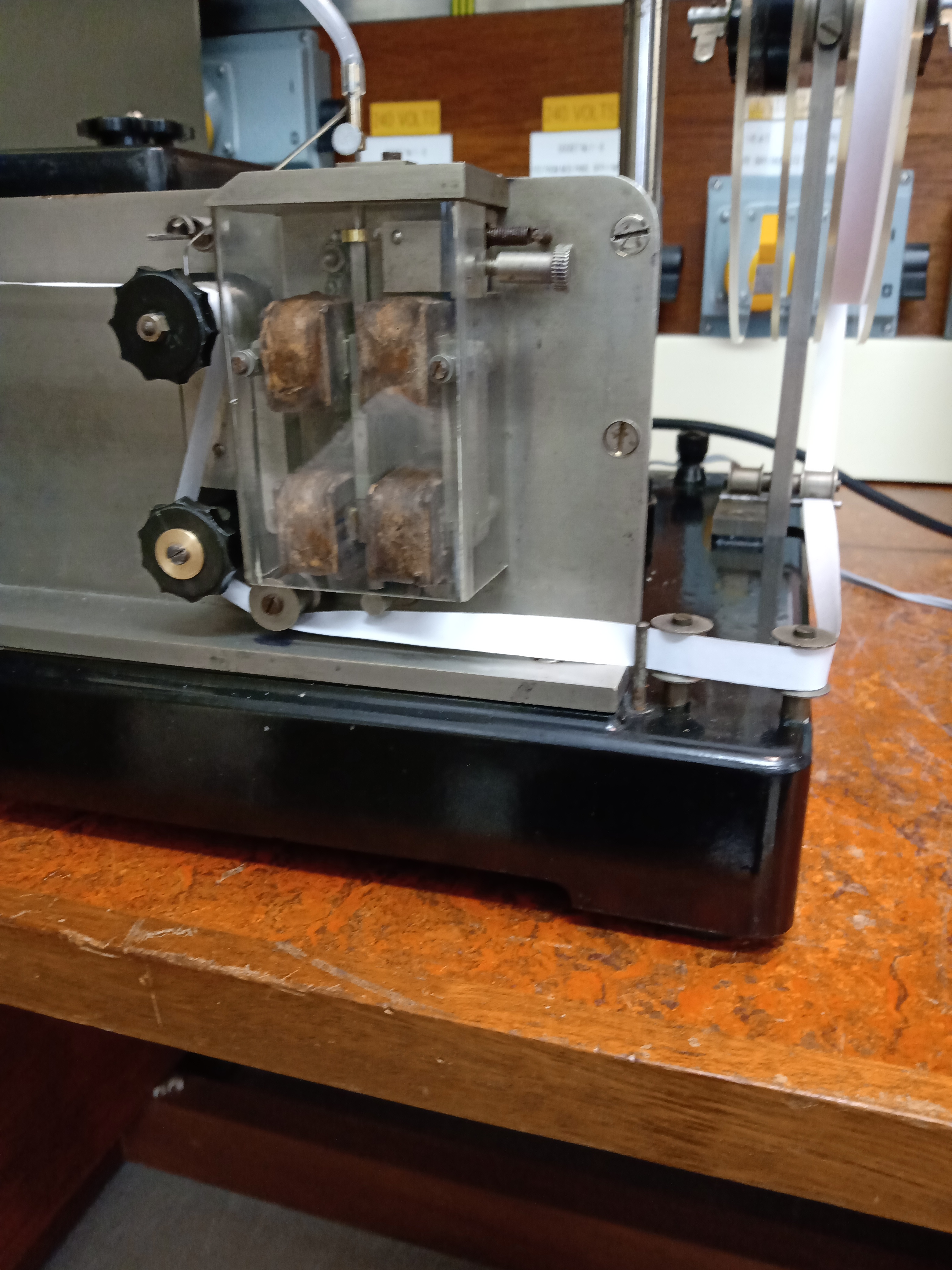
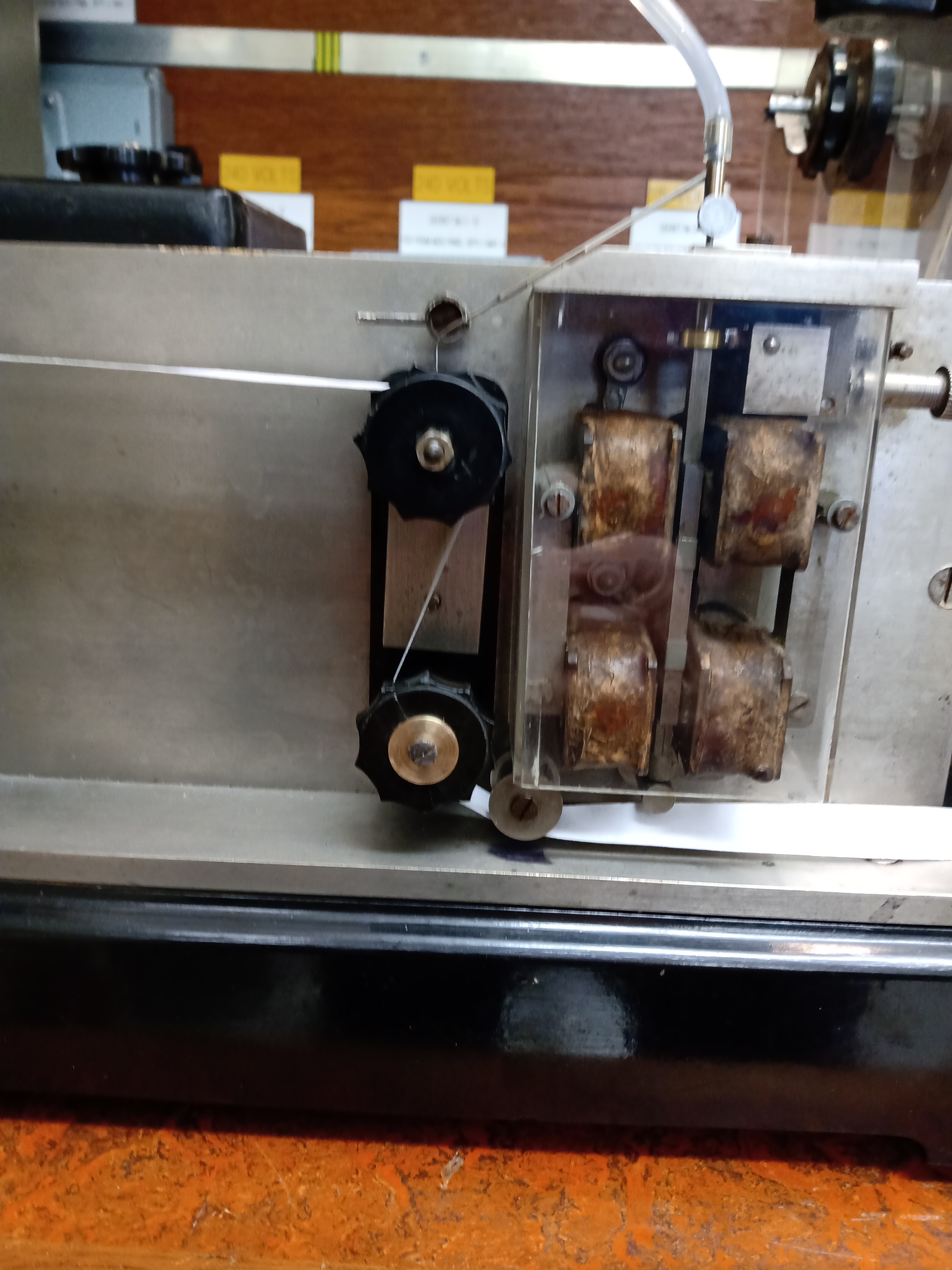
The interference suppression coils are clamped to the chassis with a strip of brass lined with felt. The felt was rotten and was replaced with synthetic foam. The 4BA bolts holding the clamp had corroded into the pillars moulded into the bakelite base. One was successfully drilled out and re-tapped. The other pillar broke off and was replaced with a turned brass male/female pillar 8.8mm by 8.8mm with 6mm of male tapped thread. This was sleeved with heat shrink sleeving, as it was in physical contact with one of the coils.
The plain bearings were oiled with 5W30 synthetic car engine oil. Hopefully this oil will not oxidise and go gummy. The ball races were washed in cellulose thinners and greased with Castrol LM car wheel bearing grease. There is some corrosion of the races and they do not run perfectly smooth but were considered to be good enough for the time being.
The ink reservoir leaked. This was mainly due to a screw fitted above the brass outlet pipe. This had corroded away completely and the rust was not completely plugging the hole. The hole was re-tapped and fitted with a hex head 6BA brass screw resembling the original. A rubber washer was cut to seal the head to the tank. It is unclear if the screw is fitted to enable a hole to be drilled in the tank, or if it is to act as a clamp for the tap. The hex head suggests the former as a /br>clamp< would have had a thumb screw.
The white ceramic fuse is fitted with the original 0.22mm fuse wire. This wire is probably copper or some other metal/alloy. The interference suppression coils have a DC resistance of 1.3 ohm and an inductance of 900uH. The undulator coils have a resistance of 650R and an inductance of 1 Henry.
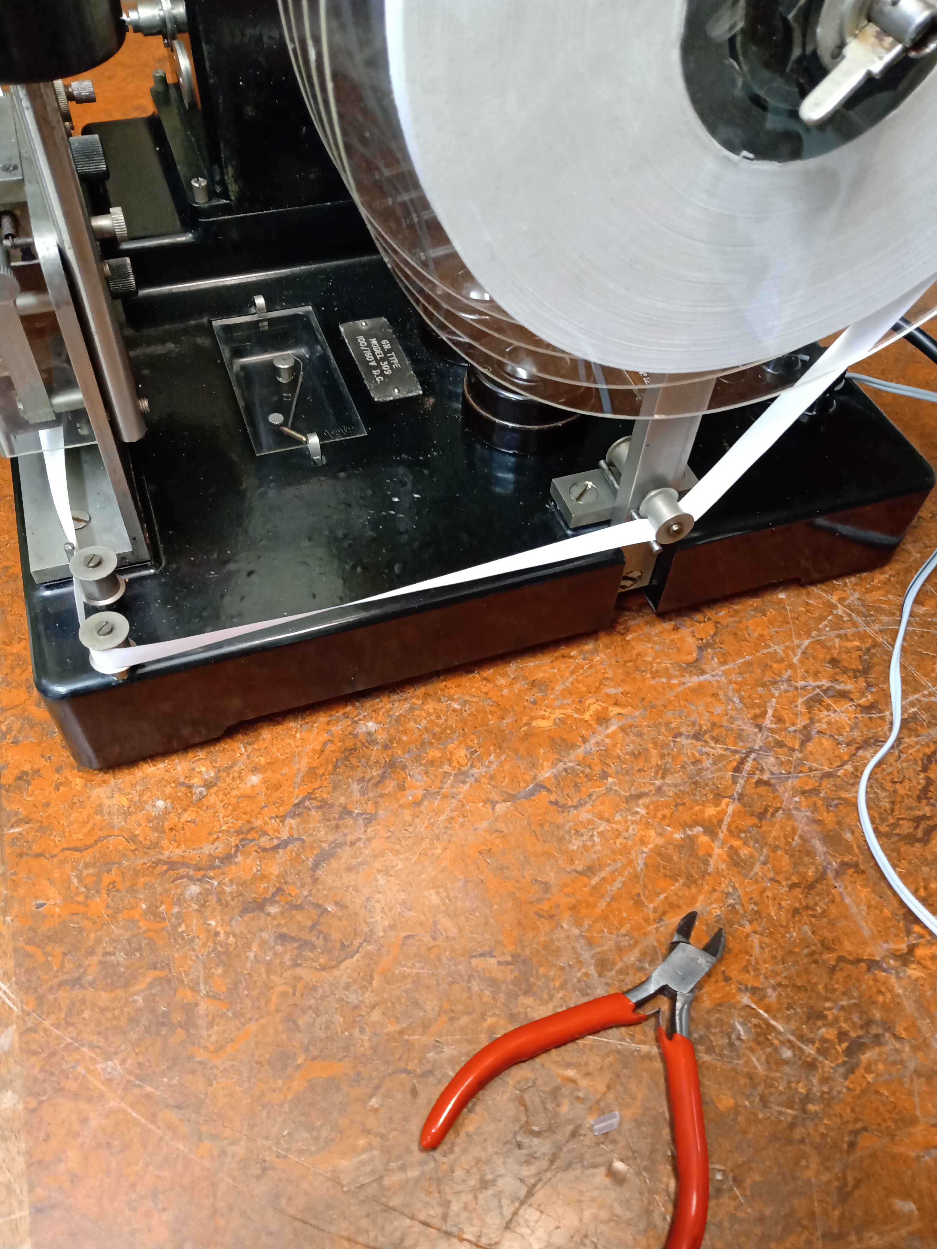
At first it seemed that paper tape would be a problem but a trawl of the internet soon found a solution. Better Equipped educational supplies sold as 9.5mm ticker tape for school science experiments. (This is used to demonstrate Newton's laws of motion). When it arrrived it had a width of 10.5mm and fitted the undulator well.
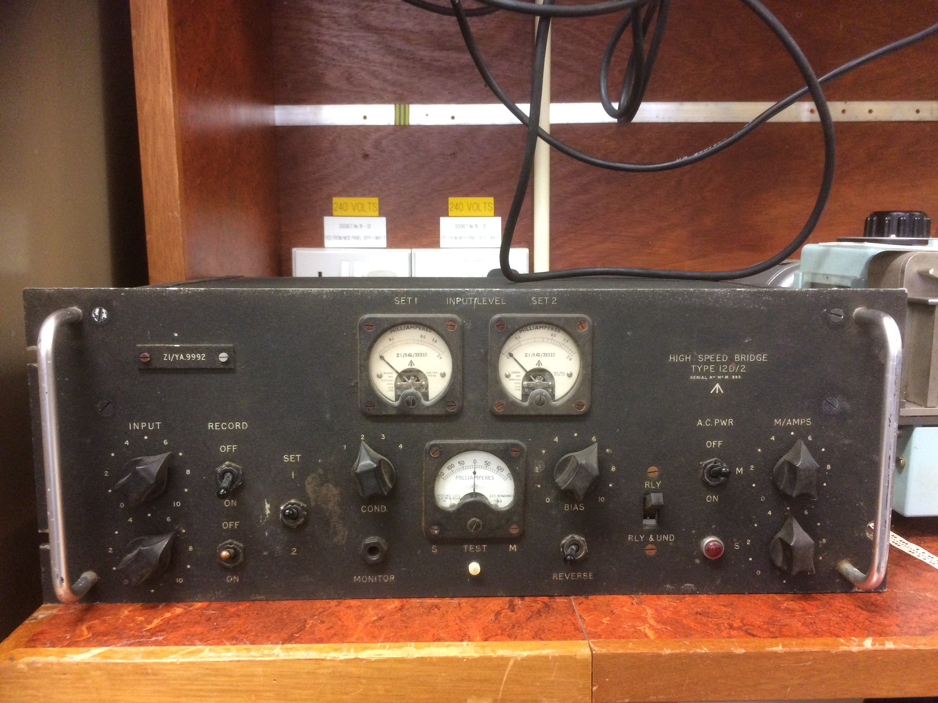
When in service, the undulator was driven by a valve operated device called a High Speed Bridge. This converted the audio output from a communications receiver/telegraph line, to pulses for the undulator coils. Undulator coils were not standardised, they could be high or low impedance. Marconi designs used moving coils. This GNT instrument is moving iron.
The undulator works to 300wpm according to a web source. Morse element (dit) length = 1200/speed in wpm. (assuming 50 bit word length such as 'Paris' or 'Morse'.) 200wpm has a dit length of 6ms, so a time constant of 1ms would seem a reasonable guess. Time constant of an L R series circuit is L/R. As the coil inductance is 1H, the circuit needs a total resistance of 1000R. As the coils need at least 20mA to operate, a 30V supply with 330R additional resistance giving 30mA seems a good starting point. It was noted that when under test at speeds of around 20wpm the tape was easily read, however, the higher the speed the more concertinaed the output became making it virtually unreadable to the untrained eye. A fully trained 'slip' operator had his/her work cut out when receiving Morse at 300wpm.
To test the undulator out a crude bridge (MK1)was built using op-amps and transistors. Click here for the circuit diagram. It was found that using a B40D receiver to drive the bridge, a good square wave could be obtained for signals down to 0.05uV at 3MHz! The bridge can be driven with a square wave to check that pen motion.
12wpm = 100ms dit period = 5Hz, 20 wpm= 8.33Hz. 100 wpm = 41.66Hz, 200wpm = 83.3Hz
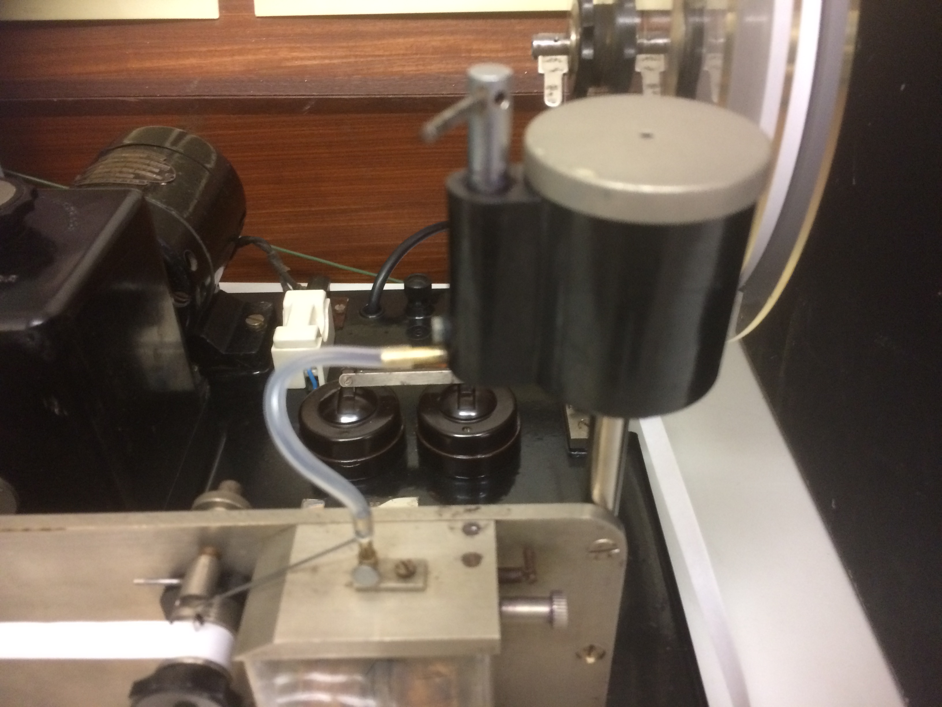
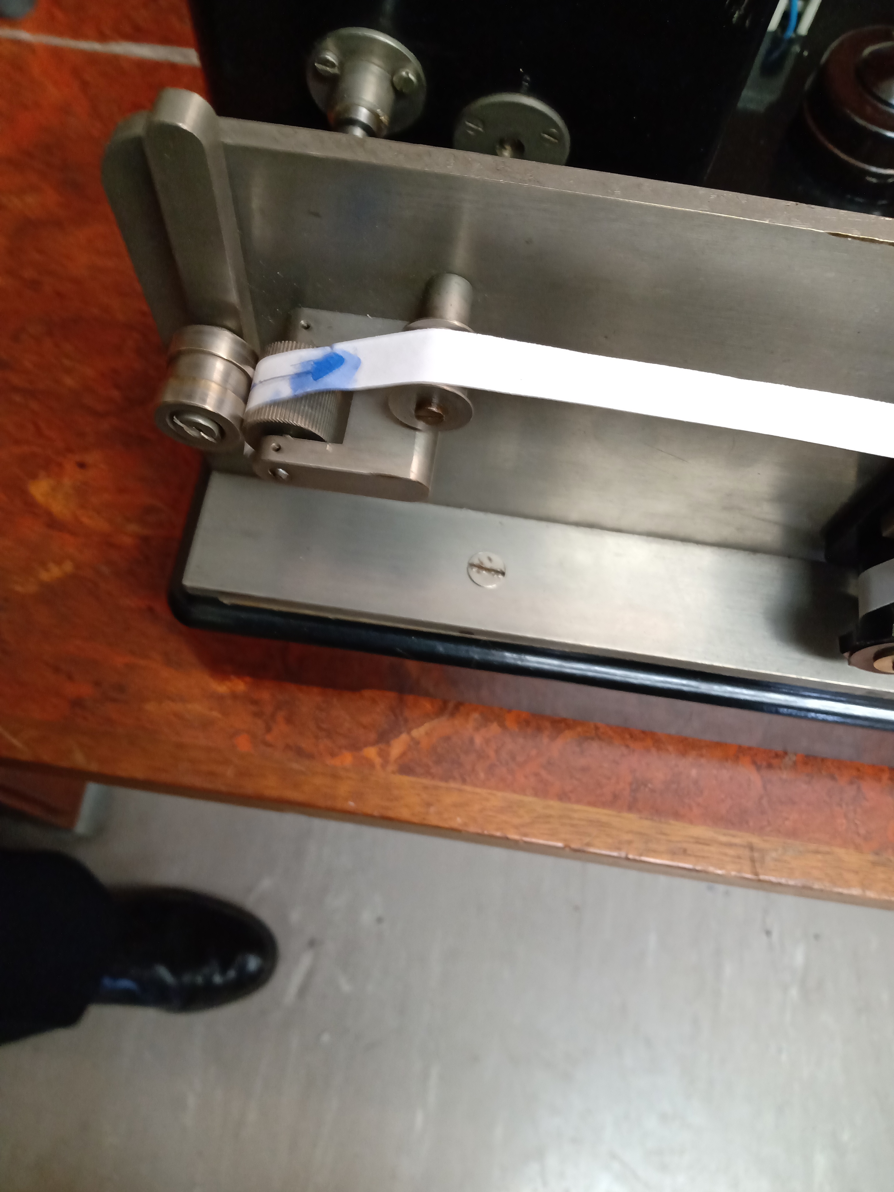
The pen is fed from the ink reservoir via a length of what looks like bicycle valve rubber tubing. This needs to be very flexible so as not to stop the pen moving. It was replaced with silicon tubing bought from ebay. Inside diameter 2.4mm, outside diameter 4mm. The ink needs to be water soluble to prevent the pen clogging. Parker Quink washable blue ink seems OK. It is probably advisable to wash out the reservoir/pen each time it is used. Note that the reservoir lifts off the machine for cleaning and the pen attaches with a thumb screw, the assembly can be lifted off as one and flushed out.
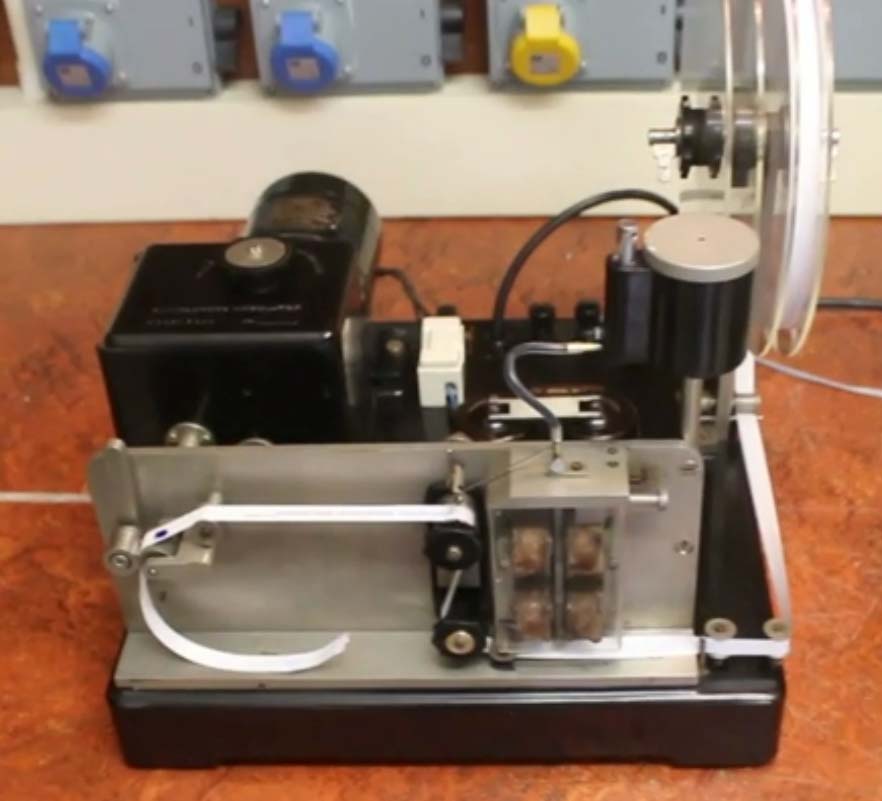
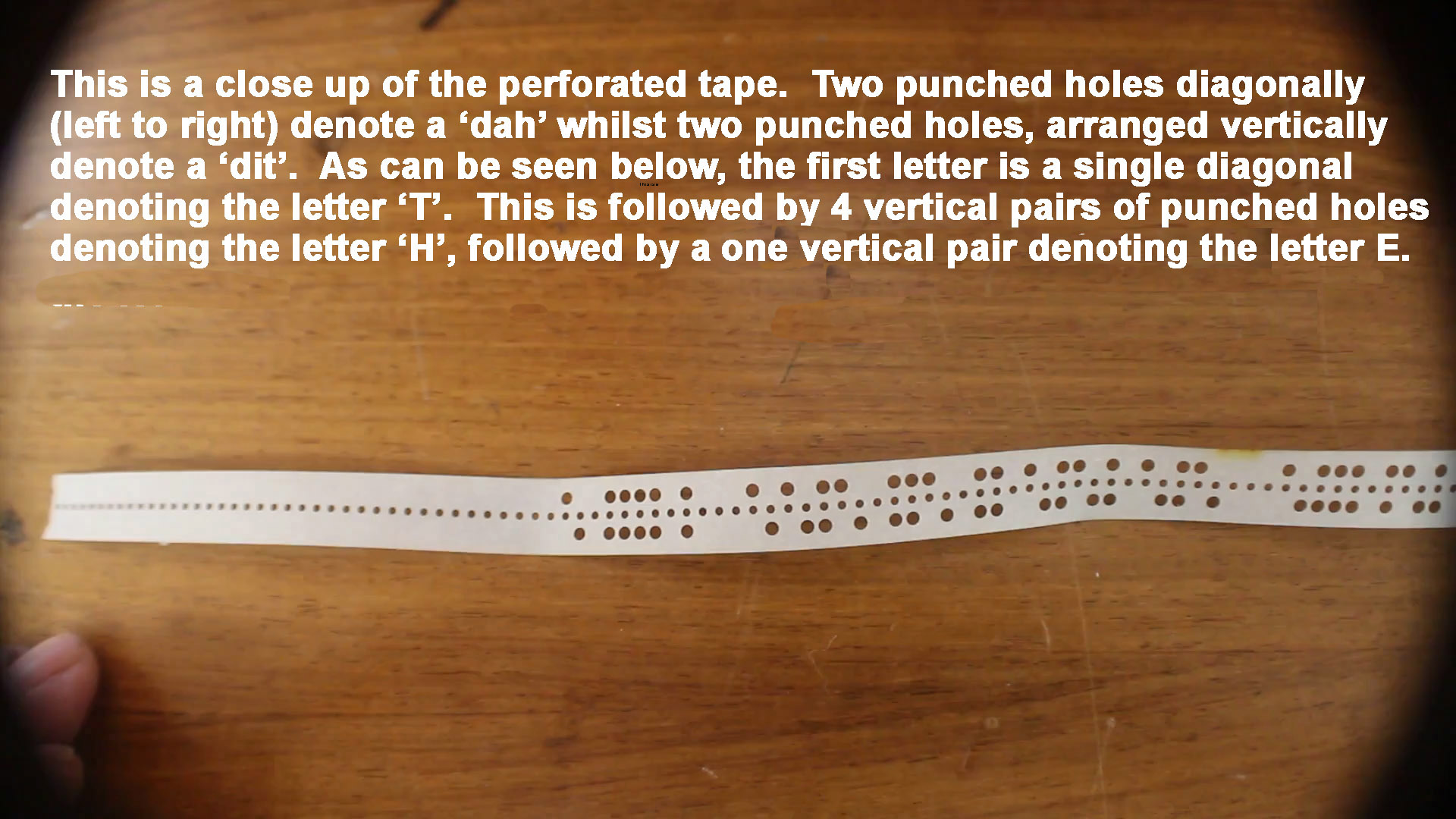
The video on the left shows the undulator undergoing a test to check that the paper tape runs through correctly. The video on the right shows the undulator undergoing its first live test. This test was conducted by connecting the undulator to the 'homebrew' High Speed Bridge (mentioned above). The Morse is provided by a GNT 112 Morse transmitter from a paper Morse tape that contains the word PARIS repeated in a loop and transmitted at 20wpm.
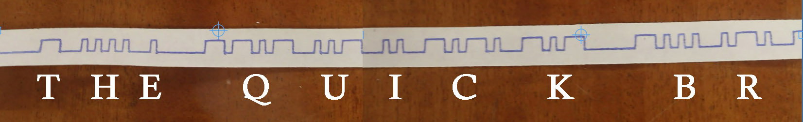
This image is of a portion of the tape seen printing out in the last video.

The next stage of the restoration is to restore a High Speed Bridge to replace the current homebrew set up. Once again we have no documents, manuals etc so it will be a case of 'suck it and see' at each stage of the restoration. The aim is to have a fully working systems whereby we can receive Morse from a receiver, an automatic transmitter or via a Morse key and get the Undulator to print it out. Watch this space.
High Speed Bridge
The GNT309 undulator needs something to convert the audio output from a communications receiver, to pulses representing morse elements to drive the undulator coils. Traditionally this device was known as a bridge, as the output stage configuration of valves and resistors resembled a Wheatstone bridge. The period valve bridge shown above was obtained from a VMARS auction, but no information could be obtained as to how it worked or what sort of undulator coils it was designed to work with. Undulators can be moving coil, or moving iron, with different coil impedances and drive requirements.
The GNT309 uses the moving iron principle and has coils measuring 650 ohms at DC and an inductance of 1H (measured with a Wayne Kerr CT492 bridge.) Experimentally a current of around 40mA gave reasonably vigorous pen movement. It seems sensible to use a similar arrangement used to drive a double current teleprinter magnet. We do not have a GNT309 manual, but we have a manual for the similar GNT310 two pen undulator. Interestingly, it does not give any information on the electrical drive requirements of the pen coils.
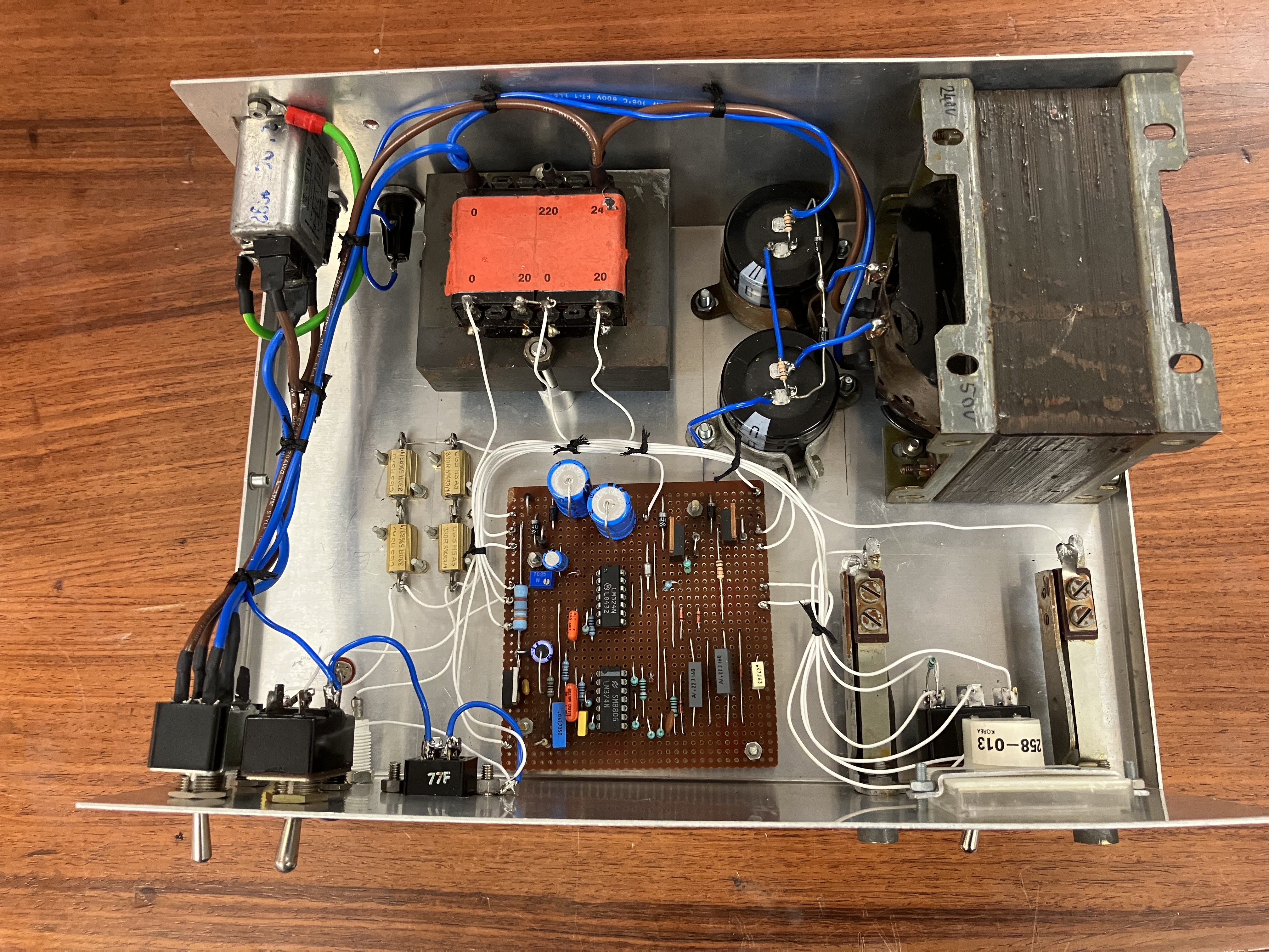
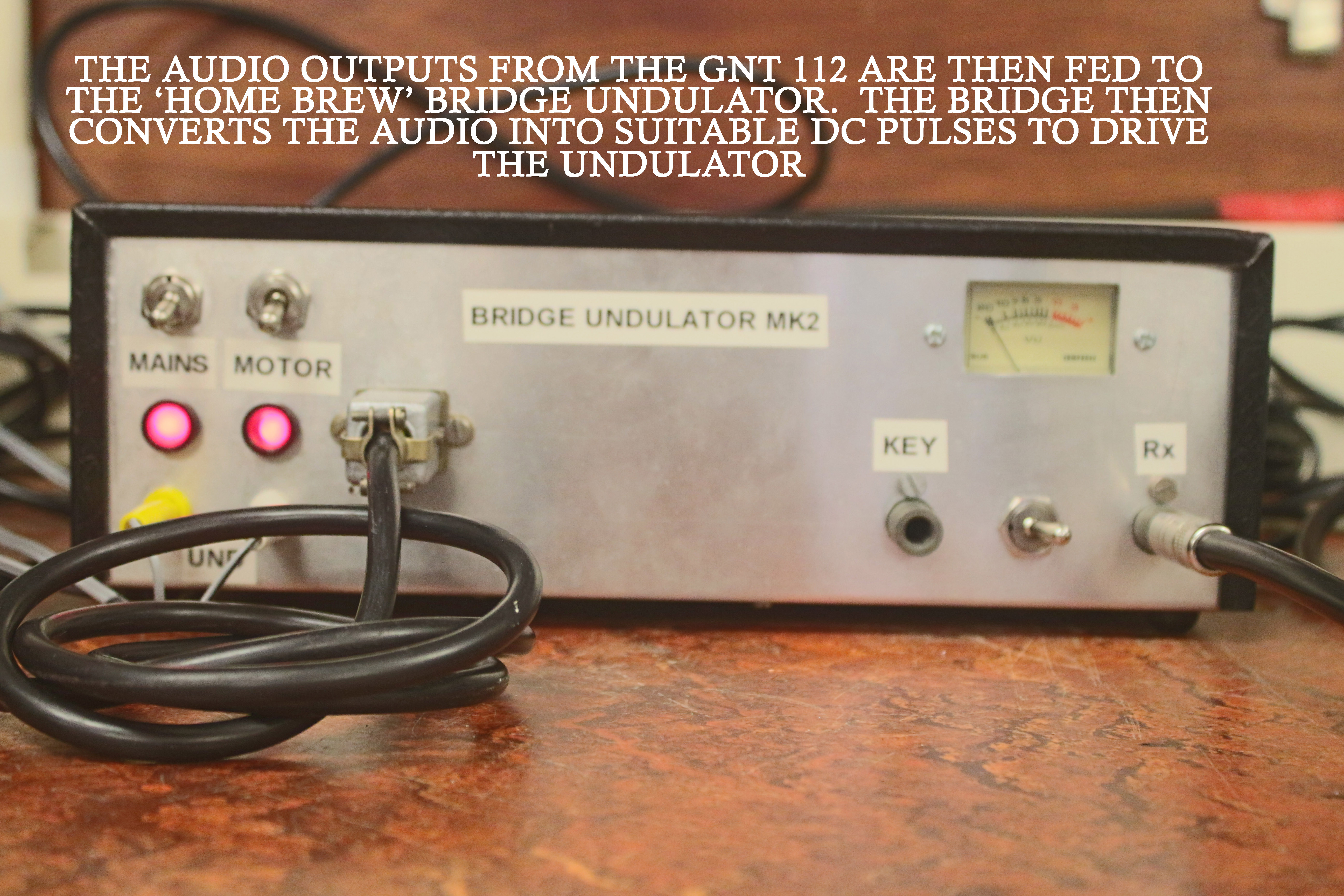
In house High Speed Bridge(MK2) inside
An improved 'home brew' MK2 bridge was built and is contained in an aluminium box and is designed to be self adjusting where possible to make demonstrations easy. It will drive the undulator coils from a morse key or morse tape auto transmitter. It will also take pulsed audio input from a tape recorder or the headphone socket of a communications receiver such as a B40. A power supply is also provided to operate the undulator motor.
Referring to the circuit diagram, (shown below) it will be seen that the device uses two LM324 quad op-amp devices and IRF510 MOSFETs in the coil driving bridge. The receiver headphone socket is connected to J2. U1B amplifies the audio signal with a gain of 46. R10 gives some protection against voltage transients. It might be worth adding back to back diodes here as belt and braces. U1D is a precision half wave rectifier. It is linear even with very small input signals, meaning that the audio input level is not that critical. U1C converts the rectifier into a full wave one. With fast morse, the beat note from the receiver may not be that different to the signalling frequency. Full wave rectification makes ripple filtering easier, as it doubles the ripple frequency. C3 removes most of the ripple from the output. D3 and D8 act as DC restorers. The morse pulse waveform is now centred around the bias voltage at the junction of R4 and R14. U2B acts as a slicer to give a 0-13V squared up version of the morse pulses. The DC restorer cannot cope with the continuous mark or continuous space condition. D2 and D9 largely get around this problem.
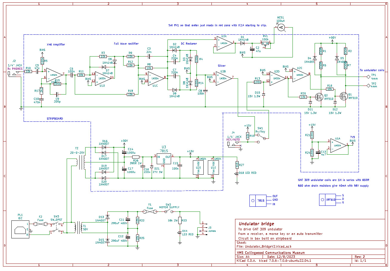 In house High Speed Bridge circuit diagram |
SW1 is a front panel toggle switch that selects either the output of the slicer or an input from a hand morse key / auto tape transmitter to be fed to the undulator coil driver. R13 and D10 protect U2D from voltage transients. U2D is used to clean up the waveform from the key input if necessary. U2C acts as an inverter. The complementary drive from these two devices, drive the gates of Q1 and Q2 so that at any one time, one device is switched hard on and the other is off. R1,2,6,7 are metal clad wire-wound resistors bolted to the chassis. They along with the coil resistance define the current through the undulator coils. D4 and D5 clamp the back EMF produced by switching to protect the MOSFETs. D11 and D12 prevent transients from the MOSFET drains, via the gate source stray capacitances, from exceeding the safe maximum gate voltage. |
U2A takes the peak voltage from the rectifier and uses it to drive a signal input meter. RV1 is set so that the meter needle is driven to the red part of the scale as the op-amps are driven into clipping. In use, the receiver audio output should be adjusted to give an indication approaching the red part of the scale. The meter also serves to show that the receiver is producing an output which has also been connected to the bridge!
There are two mains transformers used. The smaller produces 20-0-20V AC which is bridge rectified. The total voltage produced is about 56V which supplies power to the coil driver. The secondary centre tap provides about 28V which is regulated down to 15V to run the op-amps. The 7815 regulator has a maximum input voltage of 35V which might be exceeded if the mains voltage were above 240V. R26 and D21 clamp this voltage to 28V maximum. U1E and U2E are representations of the op-amp power pins for convenience in drawing the circuit diagram. U1A provides a 7.5V reference voltage labelled “BIAS” on the circuit diagram. With no input signal, the outputs of U1A, U1B, U1C, U1D, U2A, should all be at 7.5V.
The motor power supply uses a larger transformer with a 50V secondary. This is rectified by a voltage doubler to give around 140V, within the operating range of a 160V motor. LED D14 shows that the motor supply is on and that the fuse F1 has not blown. R22 and R25 are safety bleeder resistors to discharge the smoothing capacitors when the power is off.
Morse Tape - THE QUICK BROWN FOX etc
Once we had all the component parts, it was time to test it all out. We used a Creed Morse perforator that we salvaged from Corsham Mines (ex WWII underground Communication Centre) which was used to produce a Morse tape. The tape produced for the video demonstration (see below) was the proverbial THE QUICK BROWN FOX JUMPS OVER THE LAZY DOG. Note that between each letter there is one centre hole spacing whilst between words it is 3 centre hole spacing.