 |
WIRELESS TELEGRAPHY 1912© RN Communications Branch Museum/Library |
 |
 |
WIRELESS TELEGRAPHY 1912© RN Communications Branch Museum/Library |
 |
| In this file:- | General summary. Boys who joined Impregnable will commence to pass for PO Telegraphists early in 1913.
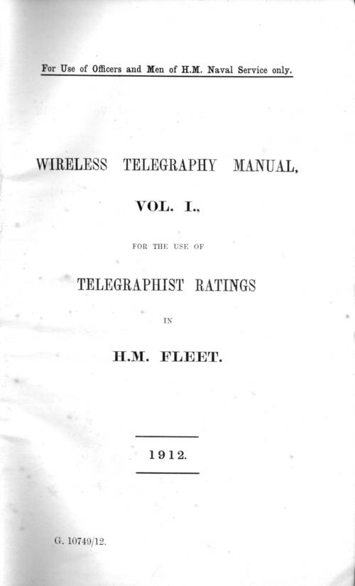
Signal and Long Distance Signal Code to be brought up to date. Vol 1 of the Wireless Manual will be issued shortly and the picture to the left is of the first page of the Manual. Design of a Mk11 set now converted to quenched spark and trials with HMS Vindictive conducted. As regards converting Mk11 generally to quenched spark is not certain. Waiting for a suitable receiver before the change over. Malta high power - Rinella - starts in 1913.
 |
||
- - - - - - - - - - - - - - - - - - - - - - - |
|||
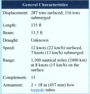
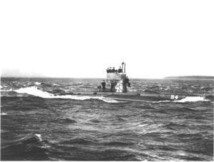
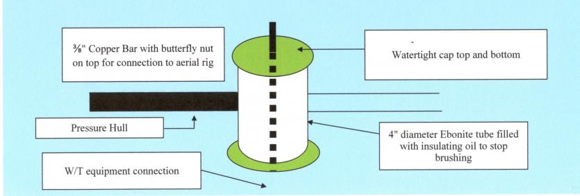
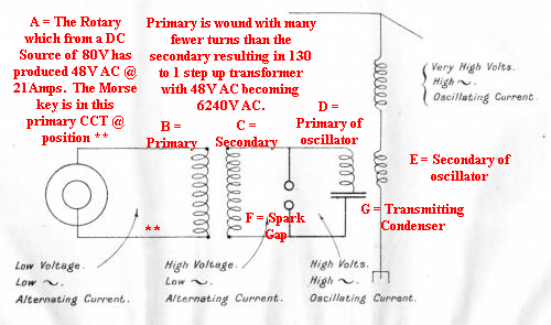
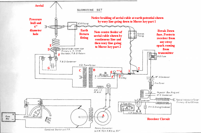
| In this file:- | Submarine Installation - the first submarine so fitted was the B5 - This was called the Type 'X' Fit.
     |
||
- - - - - - - - - - - - - - - - - - - - - - - |
|||
| In this file:- | Poulsen's experiments. Much activity in the procurement and testing of Poulsen's Arc transmitters and receivers. Power output is in doubt?? Poulsen has a monopoly in the USA having 16 x 12kW stations and 2 x 24kW stations covering thousands of miles. San Francisco is 2500 miles from Chicago and 1800 miles to Seattle. Chicago to Los Angeles in a good 1700 miles. Good/satisfactory communications would not have worked with an ordinary spark transmitter. System uses a 600V 24kW DC Generator. Switch over from transmit to receive is done in just one minute. High speed working is used occasionally. No silent cabinet, the Morse operators typing directly onto paper what they hear in their earphones. New Poulsen tikker detector. Use of Duplex. Two wavelengths, 7% apart, one from a transmitter 600 miles distant and the other 300 miles distant were received simultaneously in Los Angeles (proving the reception aerial and two receivers with varying strength of signals neither interfering with the other). Then San Francisco, using her 24kW transmitter sent two messages simultaneously, one on each wavelength each separated by 10% with good reception results (proving the transmit/receive aerial paths and the ability to radiate two signals simultaneously from one transmitter). Honolulu and San Francisco hope to maintain 24 hour a day communications using new 60kW transmitters.
New wavemeters - new designs to be issued to schools and flagships for trials.
Buzzer repeaters - which allow remote users not in the W/T office to listen to the Morse code being sent from the ship.
Silent cabinets to be lead lined to every aspect to better the current screening effects - still having problems with ventilation etc.
Browns Telegraphone relay not to be adopted. It has been found to intensify both signal interference and atmospherics with equal merit.
An emergency set has been issued for trials. It is to be used when all power fails, for boat work and for landing parties.
Sparking condenser (capacitance) values.
   |
||
- - - - - - - - - - - - - - - - - - - - - - - |
|||
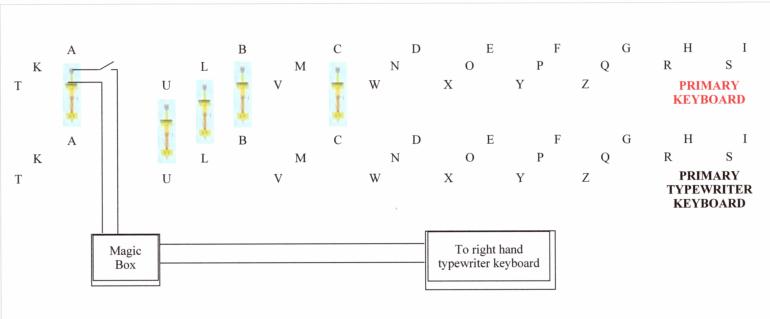
| In this file:- | Throughout these early years we have regularly mentioned the relationship of the Morse key and the receiver, both sited in the Silent Cabinet which is part of the W/T office. The transmission side, is also in the W/T office but in the high power/RF cage immediately above which is the aerial connection point and the start of the trunking system leading to the Deck Insulator (DI) to which the aerial wires are connected. In the transmit section will be found the operating switch, the protection switch and the magnetic key. The Morse key works the magnetic key which keys the transmitter.
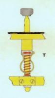
Fig 6 of this file is basic and straight forward showing the Morse key having centre stage. Notice three areas of activity in the front contact, back contact and the arm of the bar. Current flows when the key is at rest (i.e. not pressed) through one part of the circuit, and when pressed, through another part. The lamp shown is expressed as 32 CP (candle power) and when current flows the lamp is illuminated. (As a matter of interest only, candle power cannot be directly associated with today's lamp measurements viz, Watts. Have a look at the image below.
 |
||
- - - - - - - - - - - - - - - - - - - - - - - |
|||
| In this file:- | Report on Clifden W/T station May 1912. Aerial current 150 amps - pretty impressive. Main spark gap disk weighs 1 ton and rotates at 1600 revs, has 12 studs with sparking surfaces of 3" long x 1" wide. Spark cooling blower to be a 7.5 kW machine with a pressure on the spark gaps of a kindly 1.5 lbs p.s.i. Look under aerial and earth........all well stirred up in an asbestonite container ? Receivers - valves only used for standby detectors. Green or grey carborundum crystals used as primary detectors. Duplex working - awaiting Mr Marconi's next visit for final trials before going commercial. The Letterfrack station, mentioned a year ago as having taken part as a jury-rigged station in trials, has moved .5 mile to a new position with new aerials are is getting new reception kit. Clifden's aerial is a single wire over a mile long at an average height of 25 feet. Tape recording message - trial at Marconi Headquarter building in Chelmsford. Clifden will have to go high speed to keep pace with increasing traffic flows, but presently uses 20 wpm as the norm. Traffic at 40000 to 50000 words per week is already cumbersome. Glace Bay to go down to 24000 feet (40.9kHz) and suffers badly from atmospherics unlike Clifden. High speed reception at Marconi Company works. 54.25 wpm to 60 wpm achieved but faster still is a requirement. Still under trial so no fixed or published parameters. At 50 wpm, the processes (reception, recording, developing and fixing) take approximately one minute to conclude. The problem as always with high speed Morse, is that after reception, it has to be transcribed by hand which is time consuming and man-power oriented. HMS Good Hope - struck by lightning. Experiments are taking place in both aircraft and aeroplanes ? Aeroplanes are what we call anything that flies which is not a kite, a bird, insects, airships, helicopters, microlights, missiles, bullets/shells, rockets......and.....Aircraft are the same but delete airships and add aeroplanes. You are just going to love the picture at Fig 14 on page 6 of 8 in the file. Dig those aviators! Eastchurch is in Kent on the Isle-of-Sheppey where an aeroplane (hydroplane, one that uses water for its runway) that's the fixed wing type, used a destroyers harbour exercise set on a wavelength of 850 feet (1.15MHz) for a distance of 8 to 10 miles. Spark not good and got weaker as the aeroplane got higher. Aerial stretched along the wings. French system tried with aerial on wings (known as the balancing aerial) and also a trailing aerial. It was fitted to a "triple tractor bi-plane" which we think means three pieces of landing/take-off gear. In Fig 14, note the hole in the airframe through which the trailing aerial could be raised or lowered. Good musical signal on 450 feet (2.18MHz). In the aircraft (airship) W/T was tried during army manoeuvres in the "Gamma" (obviously the name of the airship). The aerial was again in two sections, the balancing section wrapped around the inside of the airship without touching its sides, and the trailing aerial, in two lengths each of 200 feet long wound up or down at will. The wavelength was 900 feet (1.09MHz) resulting in good signals out to 35 miles. The naval airship will be fitted with W/T in early 1913, and it will operate on any Service wavelength from 150 to 700 metres (2MHz to 428kHz) with ranges expected out to 150 miles. Kites - Portsmouth (Southsea Common) is famous for its Summer kite flying festival when the biggest and best compete for airspace. The 1912 kite experiments were conducted at Portsmouth to ascertain their use for receiving purposes. Pilot, single box and double box kites were used. Heights of 1200 feet achieved. Using kite combinations in various wind conditions, good results were achieved in the receiver attached to the kited-aerial. Reception went from strength 3-4 to strength 10-12. For transmission, the wavelength was four times the length of the wire aerial so a length of 265 yards gave a frequency of 308.96kHz - the newly designated 'S' Tune (where 298 kHz was the old 'S' Tune). Uses of the kite thought to be assisting ships to increasing the range of reception for long distance working for cruisers on outlying trade routes, by torpedo boat destroyers (TBD), for helping reception to be restored after battle and for use with portable sets ashore or afloat. | ||